


CM4 App Note 260424 issue 2.1.docx
Document No. 260424
Page 25 of 29
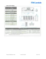
13. Connector details
PINOUTS
Circuit
Details
J1
– Mains Input
1
Live
2
Neutral
3
Earth
J2
– Standby control
1
Standby control negative
2
Standby control positive
J3
– Global Signals
1
Slot 4 - Power Good
2
Slot 4 - Inhibit
3
Slot 3 - Power Good
4
Slot 3 - Inhibit
5
Slot 2 - Power Good
6
Slot 2 - Inhibit
7
Slot 1 - Power Good
8
Slot 1 - Inhibit
9
Temperature sense (T
SNS
)
10
AC OK
11
+5V (Bias Supply 1A)
12
COM
J4 -Output Signals
1
- Sense
2
+ Sense
3
COM
4
I Control
5
V Control
6
+5V (Bias Supply 10mA)
MATING CONNECTORS
Ref.
Details
Manufacturer
Housing
Terminal
J1 - Mains Input
3 Pin, Barrier, 6-32 Steel Screws, 0.8 Nm or 7 Lb-In Torque
(1)
J2 - Standby control
2 Pin, 1.25mm, with Friction Lock, 28-30AWG
MOLEX
0510210200
0500588000
J3 - Global Signals
12 Pin, 2mm, with Friction Lock, 24-30 AWG, WIRE TO BOARD
MOLEX
0511101260
0503948051
12 Pin, 2mm, with Friction Lock, 24-30 AWG, IDT CABLE TO BOARD
MOLEX
0875681273
J4 - Output Signals
6 PIN, 1.25mm, with Friction Lock, 28-30AWG
MOLEX
0510210600
0500588000
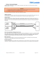
Output Power
Positive/Negative, M4 terminal, use appropriately rated crimp terminal
Notes
1. Cable 14-18AWG, 300V, 16A, 105°C, use appropriately rated crimp terminal.
2. Direct equivalents may be used for any connector parts.
3. All cables must be rated 105°C min, equivalent to UL1015