CM4 App Note 260424 issue 2.1.docx
Document No. 260424
Page 10 of 29
Specifying the CM4 product for convection or forced air cooling
To specify a CM4 series product for an end application, the required output power, minimum input line voltage, maximum ambient, mounting
orientation and air flow rate (if applicable) should be determined. Check the requirements against the closest characteristic plot from the tables
above to ensure ratings can be achieved. Be conservative when specifying the product as convection and forced air cooling can be highly
dependent on the end application enclosure and power supply mounting. The estimated performance must be verified in the end application and
temperatures may exceed predicted levels. It is also important to note that ambient temperature refers to the ambient temperature immediately
surrounding the PSU. If the PSU is mounted within an enclosure the enclosure ambient temperature is likely to be higher than the external air
ambient temperature.
Evaluating the CM4 product in the end application
To ensure the product is operating within its ratings in the end application the following procedure should be performed during the design stage.
1.
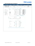
Install a thermocouple in position TS1 of the product. (See Section 12 - Mechanical dimensions and mounting for details.) The
thermocouple wire should exit on the top side between slots 2 and 3. The bottom side should be flush for heatsink mounting if
necessary. Glue should be used to hold the thermocouple in place.
2.
Setup the application in worst case conditions, considering Input line voltage, Output power, ambient temperature, airflow and cooling
restrictions.
3.
Power the system and monitor the baseplate temperature until it reaches steady state.
4.
Ensure that under worst case conditions, the baseplate temperature cannot exceed the rated temperature as outlined in the power
ratings section of this manual.
If a cover is placed over the primary components, then the following component temperatures must also be measured to ensure they are below
the maximum specified temperatures.
Description
Reference
Maximum allowed
temperature
Drawing
Fuse
FS1, FS2
125°C
Electrolytic
capacitors
C12
105°C*
Inductors
L1, L2, L3,
L5
130°C
Other capacitors
C1, C4
110°C
* For a 3 year life with 24/7 operation, the case temperature of C12 should not exceed 88C.
If excessive temperatures are measured during this evaluation, then one or more of the following remedies may improve thermal performance.
Increase heatsink size
Increase airflow rate
Improve air intake & outlet
Reduce power requirement
Using the internal temperature sensor to control external application cooling
An internal temperature sensor T
SNS
is available on J3 pin 9 (See
Internal Temperature sensor section below for details). The output voltage of
this sensor gives a measurement of the internal transformer temperature
and can be used to control external cooling systems or to provide a
warning of impending over temperature protection.
The internal temperature (T
SNS
) should never exceed 120
⁰
C (2.74V), however, system reliability will be maximised if the PSU temperature is
maintained as low as possible in any given application.


