
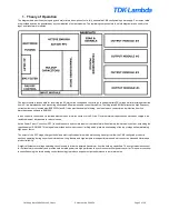


CM4 App Note 260424 issue 2.1.docx
Document No. 260424
Page 12 of 29
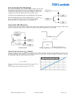
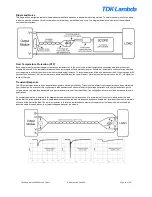
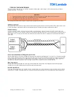
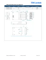
Power Good Signals (PG1-PG4 [Output])
Each output module provides a power good (PG) signal to indicate when the output
voltage is above approximately 90% of the pre-set voltage for that module. Each
PG signal on an output module is internally connected through an opto-isolator to
the signals circuit, which provides and open collector output, as shown.
The LED on the front of each module gives a visual confirmation of the PG status.
Note that remote adjustments of the output voltage using the V
CONTROL
and I
CONTROL
pins do not change the PG signal threshold. The PG threshold is always
approximately 90% of the voltage set with the manual potentiometer.
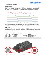
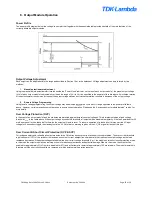
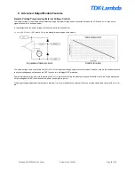
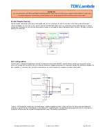
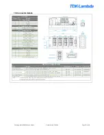
Output Inhibits (INH1-INH4 [Input])
The signals circuit provides an inhibit input to disable each output module individually. Each inhibit input is internally connected through an opto-
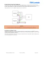
isolator to the respective output modules. The basic internal electrical circuit and timing diagrams are shown below.
Internal circuit
Timing: Typically, t
OFF
= 100 μs and t
ON
= 8 ms.
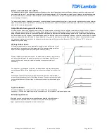
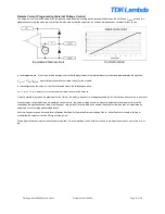
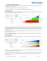
Internal Temperature sensor (T
SNS
[Output])
An internal temperature sensor is embedded in the transformer module. The output voltage of this sensor gives a measurement of the internal
transformer temperature
and can be used to control external cooling systems or to provide a warning of impending over temperature protection.
The sensor output voltage is related to temperature as follows,
V = 0.4 + 0.0195*T
The sensor will accurately measure temperatures in the range -10
⁰
C to
+125
⁰
C.
The internal temperature should never exceed 120
⁰
C (2.74V)
-20
0
20
40
60
80
100
120
0
0.5
1
1.5
2
2.5
T
SNS
output voltage Vs Internal Temperature