CM4 App Note 260424 issue 2.1.docx
Document No. 260424
Page 19 of 29
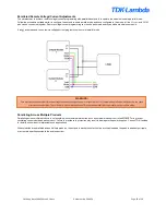
Remote Sensing
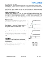
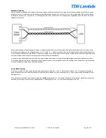
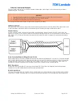
Remote sensing is available on all output modules and can be used to compensate for a voltage drop in the power leads connecting the power
supply to the load. To implement remote sensing connect the positive sense pin (S+, connector J4.2) to the positive side of the remote load and
the negative sense pin (S-, connector J4.1) to the negative side of the remote load. The voltage will be regulated at the points where the sense
cables are connected.
Active protection against damaged power cables or accidental power cable removal is provided and prevents damage to the unit in each case.
An internal circuit measures the voltage between S+ to V+ and S- to V-, when this voltage exceeds the thresholds specified in the datasheet, the
output voltage is reduced to benign levels. During system design, care must be taken to ensure power cables have a sufficiently low voltage drop
at maximum load current to ensure this protection does not activate unintentionally.
In systems where remote sensing is not used, the output voltage at the power terminals will be slightly higher than that at the sense terminals.
This voltage difference is termed,
“open sense offset” and occurs due to internal bias currents in the sensing circuit. Factory set units are set with
the sense cables connected unless otherwise specified.
Local Bias Supply
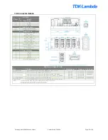
A local non-is5V bias supply is provided on each output module (+5 V on J4.6, referenced to COM on J4.3). This supply is intended to
power interface circuits for monitoring and controlling the output modules. The output can supply up to 10mA maximum, and exceeding this can
damage the unit.
Also, as COM is connected to an internal voltage that is
NOT
equivalent to S- or V-, particular attention must be given to grounding issues when
interfacing COM to any control circuit in the application. Connecting COM to S- or V- may result in damage to the unit.

