


CM4 App Note 260424 issue 2.1.docx
Document No. 260424
Page 22 of 29
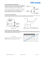
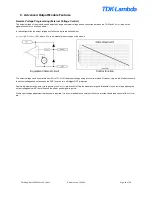
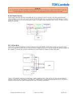
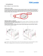
Parallel Remote Sensing
Remote sensing can be used as normal with paralleled modules. The sense lines (S+ and S-) from each of the output modules should be
connected together, S+ to S+, and S- to S- as shown below. This should be done close to the power supply output and a single pair of cables
brought from these sense lines to the load. Keeping cable lengths to a minimum and using twisted pairs where necessary will help reduce noise
pickup in the sense lines.
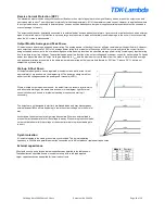
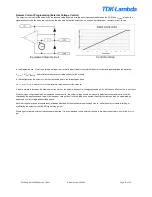
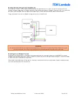
N+1 Configurations
When using N+1 redundant configurations, a suitably rated diode (or controlled MOSFET) must be used on each output to prevent a device
failure from causing a system failure. However, the diode introduces voltage drops between the supply and the load that significantly degrade the
load regulation. To counteract this, the remote sense lines can be used to regulate the voltage at the load as shown below.
Typically, this configuration can damage the internal sense resistors used within a power supply. However, the CM outputs have integrated
protection to prevent this type of damage and are completely N+1 compatible without any additional external protection circuitry. Note that only
the positive sense terminal is protected and diodes should be used in the positive connection only.
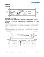
WARNING!
Care must be taken to avoid differential voltages between the negative power output terminals of share mode paralleled modules as this can cause
errors at the control pins. To avoid this, it is recommended to use TDK-Lambda parallel links to parallel modules in share mode.
.