


program
setup
program
setup
program
setup
program
setup
program
setup
program
setup
program
setup
program
setup
30.
DISCHARGE AIR
LOW LIMIT: 45F
29.
28.
ENABLE DISCHARGE
AIR SENSOR? YES
SETPOINT
OFFSET: 00F
27.
UNOCCUPIED ACTION
25.
MODULATING
MODULATING OUT
RANGE: 4-20 MA
24.
OUTPUT ACTION:
.
DIRECT
22.
MODULATING OUT
IS: COOL
21.
SET CONTROL
MODE: P+I
23.
program
setup
PROPORTIONAL
BAND: 5F
26.
program
setup
TIME CLOCK OUTPUT
OCCUPIED=CLOSED
program
setup
program
setup
program
setup
program
setup
program
setup
program
setup
program
setup
program
setup
STAGE 2
DIFF: 2F
20.
STAGE 2
OFFSET: 2F
19.
18.
STAGE 1
DIFF: 2F
STAGE 1
OFFSET: 0F
17.
STAGE OUTPUT 1&2
16.
AS: HEAT
SET OVERRIDE
TIME: 180 MINUTES
15.
LIMIT SETPOINT
14.
/-: 5F
13.
UNOCCUPIED COOL
SETPOINT: 80F
12.
OCCUPIED COOL
SETPOINT: 72F
program
setup
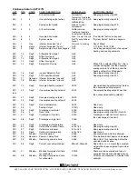
Occupied Cool Setpoint Screen.
Set
the occupied cool setpoint.
Unoccupied Cool Setpoint Screen.
Set the unoccupied cool setpoint.
User Setpoint Limit Screen.
Enter
the number of degrees you want the
user to be allowed to change the pre-
set occupied setpoints up or down.
Override Time Screen.
Enter the
number of minutes (0 to 255) that the
SZ1017N will maintain occupied set-
points when overridden.
Stage Mode Screen.
Choose whether
stages 1 and 2 perform heating or
cooling functions, or whether both
stages are to be disabled.
Stage 1 Offset Screen.
Enter an off-
set value for stage 1. First stage is nor-
mally 0 offset. This screen does not
appear if stage outputs 1 and 2 are
disabled.
Stage 1 Differential Screen.
Enter a
differential value for stage 1. This
screen does not appear if stage out-
puts 1 and 2 are disabled.
Stage 2 Offset Screen.
Enter an off-
set value for stage 2. This screen does
not appear if stage outputs 1 and 2 are
disabled.
Stage 2 Differential Screen.
Enter a
differential value for stage 2. This
screen does not appear if stage out-
puts 1 and 2 are disabled.
Control Mode Screen.
Enter whether you
want to control by temperature only (P) or
add a time factor (P+I). This applies to both
the stage outputs.
Time Clock Output Screen.
Choose
whether the auxiliary output will be OPEN
during occupied periods (and closed during
unoccupied periods) or CLOSED during
occupied periods (and open during unoccu-
pied periods).
Modulating Output Define Screen.
Choose whether the modulating output will
be used for COOL, HEAT or AQUASTAT.
With DI2 set to AQUASTAT, the analog out-
put will be used for cooling with DI2 open
and heating with DI2 closed.
Modulating Output Action Screen
.
Choose whether the output will be direct or
reverse acting. (When DI2 is set to AQUAS-
TAT, the output will automatically reverse
action when DI2 is closed.)
Modulating Output Range Screen.
Choose whether the modulating output
range will be 0-20 mA or 4-20 mA.
Unoccupied Action Screen.
Choose
whether the unoccupied action will be mod-
ulating, 0 or 4 mA, or 20 mA.
Modulating Output Proportional Band
Screen.
Enter the number of degrees away
from the setpoint that the valve or damper
will be fully open.
Analog Output Setpoint Offset Screen.
Enter a setpoint offset. This is a value below
the heating setpoint or above the cooling
setpoint where the analog output begins to
modulate.
Discharge Air Sensor Screen.
Choose whether
or not you are using the discharge air sensor
function. To monitor only, select no.See setup
instructions for dipswitch settings which must also
be set.
Discharge Air Low Limit Screen.
Enter a
discharge air low limit value. This screen
will not appear if the discharge air sensor
function is disabled.
R
2800 LAURA LANE
I
MIDDLETON, WI 53562
I
(800) 288-9383
I
FAX (608) 836-9044
I
www.tcs-basys.com
5


