background image

Description                         

The SZ1017N is a thermostat with a 7-day time clock
designed for applications with modulating heating or cooling.

Features                            

!

Stand-alone or network operation

!

7-day time clock

!

Discharge air sensor input with high and low limits and

reset 

!

Outdoor air sensor input with heating & cooling lockout

!

Offers up to two stages heating or cooling and a modulating

heating or cooling output 

!

Adjustable delay on powerup for soft starts

!

P+I control option

!

Smart Recovery

!

No backup battery required

!

Built-in HVAC equipment protection

!

32 character LCD display

!

Six LEDs for status monitoring  

!

Remote room sensing capability

!

User setpoint adjustment limits

!

Local and remote override capability 

!

System and fan switching with access lockouts  

!

Fan interlock safety option

!

Filter service input and indication

!

Equipment monitoring inputs and indication

!

External time clock input 

!

Energy management input for setpoint shift 

!

Access to programming or schedule may be locked out or

limited with the use of an access code

!

Fahrenheit or Celsius temperature display

Product Manual      

Contents                           

Description

 . . . . . . . . . . . . . . . . . . . . . . . . . . . . . . . . . . . .

1

Features

 . . . . . . . . . . . . . . . . . . . . . . . . . . . . . . . . . . . . . . .

1

Mounting

 . . . . . . . . . . . . . . . . . . . . . . . . . . . . . . . . . . . . . .

1

N2 Bus Connections  . . . . . . . . . . . . . . . . . . . . . . . . . . . . .2
Wiring

 . . . . . . . . . . . . . . . . . . . . . . . . . . . . . . . . . . . . . . . .

2

Setup

 . . . . . . . . . . . . . . . . . . . . . . . . . . . . . . . . . . . . . . . . .

3

Programming

 . . . . . . . . . . . . . . . . . . . . . . . . . . . . . . . . . . .

4

Setting Clock & Schedule

 . . . . . . . . . . . . . . . . . . . . . . . . .

7

Operation  . . . . . . . . . . . . . . . . . . . . . . . . . . . . . . . . . . . . . .7
Checkout & Troubleshooting

 . . . . . . . . . . . . . . . . . . . . . . .

9

LED Description

 . . . . . . . . . . . . . . . . . . . . . . . . . . . . . . . .

11

Limiting Occupant Access  . . . . . . . . . . . . . . . . . . . . . . . . .12
User’s Guide

 . . . . . . . . . . . . . . . . . . . . . . . . . . . . . . . . . . .

12

N2 Point Mapping Table  . . . . . . . . . . . . . . . . . . . . . . . . . .13

Mounting                         

The SZ1017N is designed for wall mounting using two #6
sheet metal screws, either over a horizontally installed 2" x 4"
junction box, or directly to block or drywall. 

For best results, the SZ1017N should be mounted on an interi-
or wall which reflects normal room environment, at a height
of approximately five feet from the floor. Avoid areas exposed
to direct sunlight, unusual heat sources, open doors and win-
dows, or unventilated locations. 

If using a remote room sensor, it should be mounted in the
manner described above. The thermostat may be mounted in
an area which is accessible for adjusting its settings. 

R

SZ1017N

Modulating Thermostat

with 7-day Time Clock

        Communicating Thermostats

R

2800 LAURA LANE 

I

MIDDLETON, WI 53562 

I

(800) 288-9383 

I

FAX (608) 836-9044 

I

www.tcs-basys.com

1

Содержание SZ1017N

Страница 1: ...e locked out or limited with the use of an access code Fahrenheit or Celsius temperature display Product Manual Contents Description 1 Features 1 Mounting 1 N2 Bus Connections 2 Wiring 2 Setup 3 Progr...

Страница 2: ...ughout because these are half wave recti fied devices SZ1017N thermostats require 8 VA 24 VAC When the SZ1017N is used as a stand alone thermostat with out communications the unit transformer may be u...

Страница 3: ...e two set screws located at the top right and the left side to prevent tampering Setup Note If using remote sensor s the calibration may need to be adjusted See Checkout and Troubleshooting section SE...

Страница 4: ...S TEMPS SHOWN IN 4 FAHRENHEIT program setup Main Monitoring Screen Press the pro gram setup button to access the following screens Access Code Entry Screen Will appear if access code is required for p...

Страница 5: ...pear if stage outputs 1 and 2 are disabled Stage 2 Differential Screen Enter a differential value for stage 2 This screen does not appear if stage out puts 1 and 2 are disabled Control Mode Screen Ent...

Страница 6: ...by 1 degree for cooling Outdoor Air Sensor Screen Choose whether or not you are using an outdoor air sensor function To monitor only select no See setup instructions for dip switch settings which must...

Страница 7: ...l be maintained and the fan will operate according to its unoc cupied setting The occupied LED will be lit when the unit is operating in the occupied mode The occupied schedule may be set utilizing th...

Страница 8: ...ns or dis charge air reset function See Discharge Air Reset section for further programming options If NO is chosen the dis charge air is still monitored When the function is enabled a LOW LIMIT and H...

Страница 9: ...ences to protect equipment The fan has a minimum on and off time of 30 seconds When the fan is in AUTO or COOL mode it will come on 30 seconds before the heating or cooling stages are allowed to seque...

Страница 10: ...roubleshooting section TROUBLESHOOTING No Display Check for 24 VAC on terminals 24 and 24 Check the cable connecting the cover to the base for a good connec tion Fan Does Not Come On The fan is on whe...

Страница 11: ...a PC Additional monitoring is available by continually pressing the service key MON 72F 12 00 AM DISCHARGE AIR 55F OUTDOOR AIR OVERRIDE ON 178 MINUTES 75F HEAT STAGE 1 OFF MOD OUT 100 SERVICE STATUS O...

Страница 12: ...ry default the unit will remain in the occupied mode for 180 minutes This value may be changed from 0 to 255 minutes in programming step 15 FAN SWITCHING The option to allow the occupant to change th...

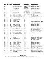
Страница 13: ...0 90 Occupied heating setpoint must be less than occupied cooling setpoint ADI 20 DegF Unoccupied heating setpoint 40 90 Unoccupied heating setpoint must be less than unoccupied cooling setpoint ADI 2...

Страница 14: ...itch 0 No 1 Yes Enables System Switch button BD 5 Use of discharge air sensor 0 No 1 Yes Always monitored enables discharge air function BD 6 Use of outdoor air sensor 0 No 1 Yes BD 7 Enable smart rec...

Страница 15: ...it 0 OK 1 Below Read only Discharge air function low limit BD 41 DI2 service status 0 OK 1 Check DI2 Read only DI2 Service NOTE 1 The Service status point represents general Check status if this is po...

Страница 16: ...Rev 1000 R 2800 LAURA LANE IMIDDLETON WI 53562 I 800 288 9383 IFAX 608 836 9044 Iwww tcs basys com 16...

Отзывы: