


●
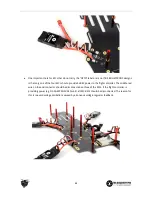
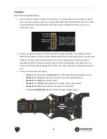
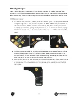
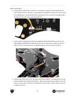
The channels with a text label, i.e. PPM, GIMBAL_ROLL, GIMBAL_PITCH, CAM_SWITCH and
RSSI_ANALOG, has the signal pin (
∏
) hardwired directly to their respective electronics section on the
top frame (i.e. flight controller PPM break-out, gimbal controller roll/tilt, camera switcher, and CORE
RSSI signal). No further wiring is needed to enable those systems.
●
Either gimbal channels and/or camera switch channel can be omitted if desired to free up channels (e.g.
to use a 6/7 channel PWM receiver.) But you will of course lose direct control over those systems.
●
See the “FPV gear and gimbal” in the electronics installation section for further details.
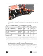
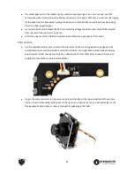
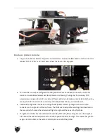
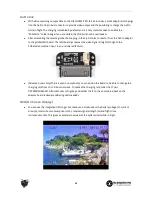
R/C receiver
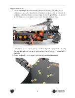
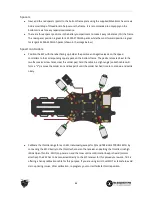
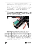
●
Plug in the short servo extensions on the header on the top plate and connect them to the R/C receiver.
Use a self-adhesive foam pad to mount the unit to the back-end of the top plate. Mount the antenna(s)
in a vertical and/or “V”-formation using nylon antenna tube(s).
●
Channel 5, 6 and 8 pin headers can be used for other purposes (e.g., NAZA X1, X2) by disabling the
gimbal R/C mapping via SimpleBGC (BaseCam) and/or camera switcher via CORE Menu.
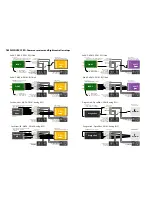
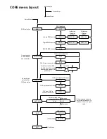
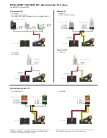
R/C receiver
Ch. 1
Ch. 2
Ch. 3
Ch. 4
Ch. 5
Ch. 6
Ch. 7
Ch. 8
Flight
controller
Aileron/P
PM
Elevator
Throttle
Rudder
Gimbal
Roll
Gimbal
Pitch
Flight
mode
Camera
switch
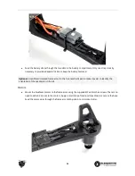
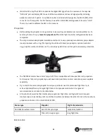
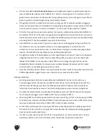
●
When using the RSSI (Received Signal Strength Indication) signal from a compatible R/C receiver, use
the header labeled RSSI_ANALOG to supply the signal directly to the CORE. Or, leave the header unused
and connect the output to your OSD system of choice.
29
Содержание Quadrotor
Страница 37: ... CORE menu layout Button Enter use up ...


