

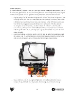
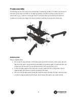
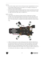


Spacers
●
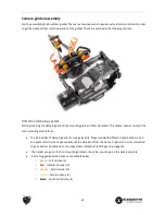
Next, add the red spacers (posts) to the bottom frame plate using the supplied M3x6.5mm hex screws.
Add a small drop of threadlock to help secure the frame. It is recommended to only apply on the
bottom screws for easy repairs/maintenance.
●
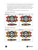
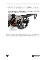
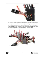
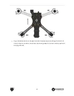
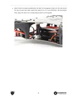
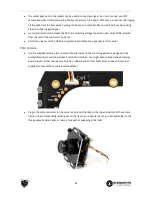
There are three spacer positions in the battery compartment to make it easy to balance (CG) the frame.
The rear spacer position is great for 4S 3300-3700mAh packs, while the most forward position is great
for larger 4S 4000-4500mAh packs (shown in the image below.)
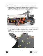
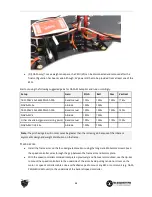
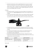
Speed controllers
●
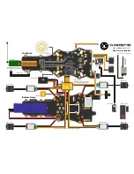
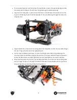
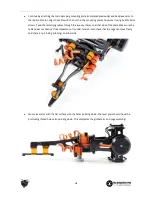
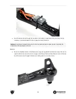
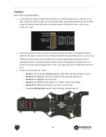
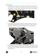
Position the ESC with the label facing up. Solder the positive and negative leads on the speed
controllers to the corresponding square pads on the bottom frame. The pads are located next to the
two frame arm screw holes. Heat the solder pad, hold the cable in a slight angle (so both cables will
form a “V”), remove the solder iron and keep still until the solder has had time to cool down and settle
nicely.
●
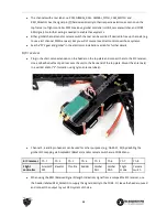
Calibrate the throttle range for each ESC individually (except for DJI and TBS BULLETPROOF ESCs) by
connecting the ESC directly to the throttle channel on the receiver and setting the throttle stick high
(Wide Open Throttle - WOT) on power-on and then low until a confirmation beep is heard (motors
attached). The ESC has to be connected directly to the R/C receiver for this procedure to work. TBS is
offering a handy calibration cable for this purpose. If you are using EzUHF, set WOT as failsafe to avoid
start-up timing issues. After calibration, re-program your correct failsafe throttle position.
22
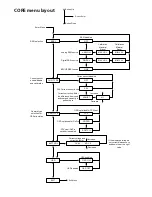
Содержание Quadrotor
Страница 37: ... CORE menu layout Button Enter use up ...


