6-2
OPERATING PROCEDURES
Model C706
Operating Procedures
6
2.
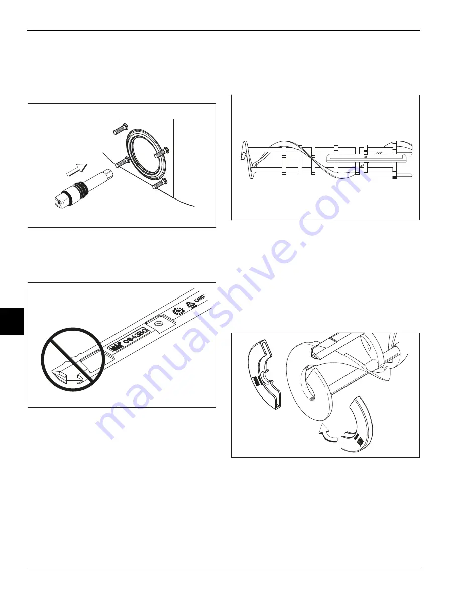
Insert the driveshaft into the freezing cylinder (hex
end first) and into the rear shell bearing until the seal
fits securely over the rear shell bearing. Engage the
hex end firmly in the drive coupling. Make sure the
driveshaft fits into the drive coupling without binding.
Figure 6-2
3.
Before installing the beater assembly, inspect the
scraper blades for any signs of wear or damage. If a
scraper blade is nicked or worn, replace both blades.
Figure 6-3
4. Place the rear scraper blade over the rear holding pin
on the beater.
Note:
The hole on the scraper blade must fit
securely over the pin to prevent costly damage.
Figure 6-4
5. Holding the rear blade on the beater, slide it halfway
into the freezing cylinder. Install the front scraper
blade over the front holding pin.
6. Before installing the beater shoes, check them for
any nicks, cracks, or signs of wear. If any defects are
present, replace the beater shoes.
7. If the beater shoes are in good condition, install
them.
Figure 6-5
8. Slide the beater assembly the rest of the way into the
freezing cylinder.
Make sure the beater assembly is in position over the
driveshaft. Turn the beater slightly to be certain it is
properly seated. When in position, the beater should
not protrude beyond the front of the freezing cylinder.
11230
11529
11256
11532
Содержание C706
Страница 8: ...1 4 TO THE INSTALLER Model C706 To the Installer 1 Notes ...
Страница 14: ...3 4 SAFETY Model C706 Safety 3 Notes ...
Страница 36: ...6 14 OPERATING PROCEDURES Model C706 Operating Procedures 6 Notes ...
Страница 42: ...8 4 TROUBLESHOOTING GUIDE Model C706 Troubleshooting Guide 8 Notes ...
Страница 44: ...9 2 PARTS REPLACEMENT SCHEDULE Model C706 Parts Replacement Schedule 9 Notes ...
Страница 48: ...10 4 LIMITED WARRANTY ON EQUIPMENT Model C706 Limited Warranty on Equipment 10 Notes ...
Страница 52: ...11 4 LIMITED WARRANTY ON PARTS Model C706 Limited Warranty on Parts 11 Notes ...


