background image

OPERATING PROCEDURES

6-11

Model C303 & C314

Operating Procedures 

 6

5.

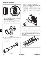
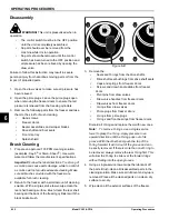
Allow the rinse water to flow into the cylinder 
until it is approximately 2/3 full. With a pail under 
the door spout, open the draw valve and drain 
the rinse water. 

Repeat this procedure 

until the 

rinse water being drawn is clear

6.

Repeat step 1 through step 5 for the remaining 

freezing cylinder.

7.

When draining is complete, press the OFF (<- -) key.

Cleaning

1.

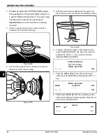
Prepare an approved 100 PPM cleaning solution. 

(examples: 2-1/2 gal. [9.5 liters] Kay-5

®

 or 2 gal. [7.6 

liters] Stera- Sheen

®

). Use warm water and follow the 

manufacturer's specifications.

Important! 

Make sure the cleaner is completely      

dissolved.

2.

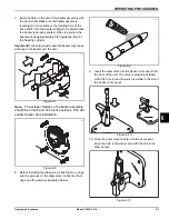
Pour the cleaning/sanitizing solution into a clean, 

empty pail. Place the syrup line with the old syrup 

connector into the pail of cleaner.

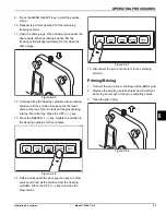
3.

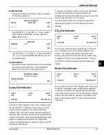
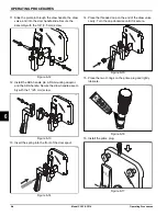
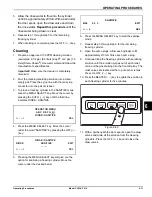
To place a freezing cylinder in the SANITIZE mode, 

press the MENU SELECT key. Move the cursor by 

pressing the AUTO (- ->) key until the third line 

indicates RINSE / SANITIZE.

4.

Press the MENU SELECT key. Move the cursor 

under the word "SANITIZE" by pressing the OFF (<- -

) key.

5.

Pressing the MENU SELECT key will give you the 

option for sanitizing a freezing cylinder. Move the 

cursor under the desired barrel.

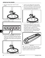
6. Press the MENU SELECT key to start the sanitize 

mode.

7. Repeat step 3 through step 6 for the remaining 

freezing cylinder.

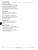
8. Open the prime plugs. Allow each cylinder to fill 

approximately 2/3 full. Close each prime plug.

9. Continue filling the freezing cylinders with sanitizing 

solution until the solution purges out of each relief 

valve and begins draining into the front drip tray. The 

relief valves are located at the top of each mix tank. 

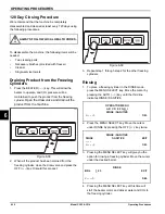
Press the OFF (<- -) key.

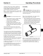
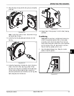
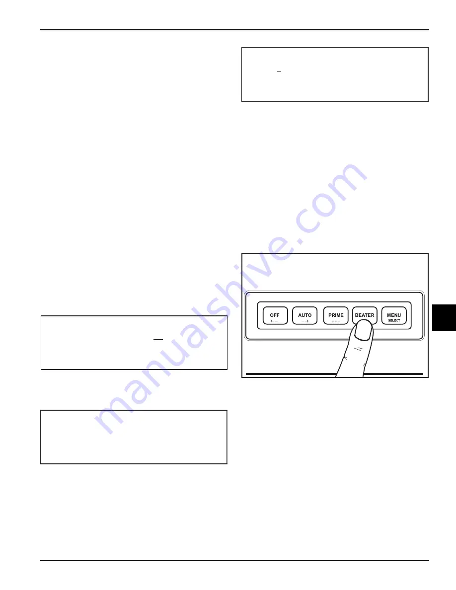
10. Press the BEATER (- - -) key to agitate the solution in 

each freezing cylinder for five minutes.

Figure 6-40

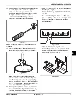
11. With a pail beneath the door spouts, open the draw 

valves and drain all the solution from the freezing 

cylinders. Press the OFF (<- -) key and close the 

draw valves.

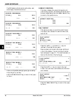
OPERATOR MENU

A B C D E F G H I

RINSE / SANITIZE

L

E

S

>

-

-

-

-

<

RINSE / SANITIZE

RINSE

SANITIZE

EXIT

- - - - -

L

E

S

>

-

-

-

-

<

SEL 

<- - - -> 

EXIT 

BRL 1 

SANITIZE

13040

Содержание C303

Страница 1: ...OPERATOR S MANUAL Model C303 C314 Slush Freezer 08 19 10 Original Publication Updated 1 23 2019 Original Operating Instructions 066732 M...

Страница 2: ...____ Cycle__________ Phase__________________________________ Maximum Fuse Size ______________________________________________________ A Minimum Wire Ampacity __________________________________________...

Страница 3: ...arranty Disclaimer 2 2 Section 3 Safety Section 4 Operator Parts Identification C303 4 1 Model C314 4 2 Beater Door Assembly 4 3 Accessories 4 4 Section 5 User Interface Control Switch 5 1 Liquid Crys...

Страница 4: ...Cylinders 6 10 Rinsing 6 10 Cleaning 6 11 Disassembly 6 12 Brush Cleaning 6 12 Section 7 Operator Checklist During Cleaning and Sanitizing 7 1 Troubleshooting Bacterial Count 7 1 Regular Maintenance C...

Страница 5: ...orming any repairs Failure to follow this instruction may result in personal injury or death from electrical shock or hazardous moving parts as well as poor performance or damage to the equipment Note...

Страница 6: ...pressure Improper water adjustments may cause operation discrepancies Water Connections An adequate cold water supply must be provided with a hand shutoff valve On the back of the unit a 3 8 in 9 5 mm...

Страница 7: ...quipotential bonding symbol 5021 of IEC 60417 1 on the removable panel and the frame NOTICE Stationary machines which are not equipped with a power cord and a plug or another device to disconnect the...

Страница 8: ...liquid Filling the cylinder to approximately 80 will allow for normal expansion CAUTION Use only approved refrigerant listed on the machine s data label or authorized through a manufacturer s technic...

Страница 9: ...ibutor for service Note Your Taylor warranty is valid only if the parts are authorized Taylor parts purchased from the local authorized Taylor distributor and only if all required service work is prov...

Страница 10: ...gerant used in its equipment For example if the refrigerant is lost during the course of ordinary service to this unit Taylor has no obligation to either supply or provide replacement refrigerant eith...

Страница 11: ...an equipotential grounding lug that is to be properly attached to the rear of the frame by the authorized installer The installation location is marked by the equipotential bonding symbol 5021 of IEC...

Страница 12: ...evere personal injury from blade contact USE EXTREME CAUTION when removing the beater assembly The scraper blades are very sharp WARNING This unit is pressurized when in operation The control switch m...

Страница 13: ...e Only This unit is designed to operate indoors under normal ambient temperatures of 70 F to 75 F 21 C to 24 C The freezer has successfully performed in high ambient temperatures of 104 F 40 C at redu...

Страница 14: ...3 4 SAFETY Model C303 C314 Safety 3 Notes...

Страница 15: ...Description Part No 1 Panel Side Left 059721 2 Panel A Rear X66671 3 Panel Side Right 059722 4 Display LED C303 P O P 066670 5 Panel Front Upper 066682 6 Panel Front Shell 66647 Item Description Part...

Страница 16: ...em Description Part No 1 Display LED 15 4 Tall 68575 2 Panel Side Left 59721 3 Panel A Rear X68182 4 Screw 10 32X1 2 SLTD TRUS 37734 5 Panel Front Upper 68496 6 Panel Front Shell 059576 SPN Item Descr...

Страница 17: ...Black 039321 9 O ring 9 32 OD X 1 16 Wall 046193 BLA 10 Plug Prime Slush Press 053869 11 O ring 5 1 4O D X 210W 029751 12 Nut Spout Door Slush 039568 13 O ring 1 129 ODX 989IDX 070 039219 14 Screw 10...

Страница 18: ...055492 100 2 oz packs or Kay 5 part no 041082 200 packs 1 2a 2b 4 2c 2d 5 3 2 Item Description Part No 1 Pail Mix 10 qt 013163 2 Brush A Package X64275 2a Brush Mix Pump Body 3 X 7 023316 2b Brush DBL...

Страница 19: ...position this control switch allows machine operation Liquid Crystal Display There is one Liquid Crystal Display LCD located on the upper front panel behind the illuminated display The LCD shows the...

Страница 20: ...he syrup systems in each freezing cylinder As long as syrup is available the word OK will appear on the LCD When the syrup supply is insufficient the word OUT will flash on the LCD The same rules appl...

Страница 21: ...n use the AUTO key to cycle to MENU ITEM A then press the MENU SELECT key Screen B is FAULT DESCRIPTION The fault description screen will indicate if there is a fault in one of the freezing cylinders...

Страница 22: ...g tone will clear H2O PRESSURE LOW When the water out indicator displays a lack of water a 60 second internal timer will start If the water is not replenished at the end of the 60 seconds all freezing...

Страница 23: ...the DEFROST mode the barrel will begin heating but the software will not attempt to run the beater for 10 minutes This gives the beater motor time to cool down from its internal overload If the barrel...

Страница 24: ...T key accepts the selec tion and displays a screen similar to the following This screen will initially show the setting that is cur rently in use Pressing the AUTO and OFF keys moves the cursor right...

Страница 25: ...umber of the language and text The fourth feature will display the Power Saver mode OFF REST or STANDBY status If the Power Saver Mode is OFF the following screen will be displayed If a Power Saver mo...

Страница 26: ...the fault page Page numbers are located in the upper right hand corner of the display The most recently recorded fault will appear on page 1 1 The fault description is listed on the third line of the...

Страница 27: ...barrel will enter the Hold mode During the Hold mode refrigeration remains off the beater continues to run if the barrel is less than 50 F 10 C and the CO2 solenoid for that barrel is closed to preve...

Страница 28: ...there is an OUT condition for syrup water or CO2 When the light is flashing it indicates that the product is not at serving viscosity This will occur during the initial freeze down a defrost cycle an...

Страница 29: ...r instructions at the point where the parts are disassembled and laid out to air dry The following procedures will show you how to assemble the parts into the freezer sanitize them and prime the freez...

Страница 30: ...and evenly lubricate the end of the seal that fits onto the rear shell bearing 5 Insert the beater drive shaft into the freezing cylinder slotted end first and into the rear shell bearing until the se...

Страница 31: ...ater and the door Figure 6 7 Note The scraper blades on the beater assembly should be in the 6 and 12 o clock positions This will enable freezer door installation Figure 6 8 8 Before installing the dr...

Страница 32: ...pin ADA mounting adaptor and the ADA handle Secure the draw handle assem bly with the 1 25 mm screw Figure 6 13 13 Insert the spring into the front of the door spout Figure 6 14 14 Place the threaded...

Страница 33: ...l the four handscrews on the studs and finger tighten them equally in a crisscross pattern to ensure that the door is snug Do not overtighten the handscrews Figure 6 20 20 Repeat step 1 through step 1...

Страница 34: ...syrup bag Figure 6 23 5 With the bag connector attached to the syrup line place the syrup line into the pail of sanitizing solution Figure 6 24 6 To place a freezing cylinder in the Sanitize mode pres...

Страница 35: ...e relief valve at the top of the mix tank and begins draining into the front drip tray Press the OFF key 13 Press the BEATER key Agitate the solution in the freezing cylinders for five minutes Figure...

Страница 36: ...ow the product to flow into the cup Close the syrup sampling valve by turning the handle to the center position Figure 6 32 9 Stir the finished product Pour a small amount of product over the refracto...

Страница 37: ...ct flow The down position opens the syrup sampling valve for collecting brix samples The center position shuts off the product flow The up position directs the flow of product to the freezing cylinder...

Страница 38: ...as been drained from the freezing cylinder close the draw valve and press the OFF key Discard this product Figure 6 39 3 Repeat step 1 through step 2 for the other freezing cylinders Rinsing 1 To plac...

Страница 39: ...the third line indicates RINSE SANITIZE 4 Press the MENU SELECT key Move the cursor under the word SANITIZE by pressing the OFF key 5 Pressing the MENU SELECT key will give you the option for sanitiz...

Страница 40: ...all brushes provided with the freezer are available for brush cleaning 2 Return to the freezer with a small amount of cleaning solution With a single service towel wipe clean the rear shell bearing s...

Страница 41: ...OPERATING PROCEDURES 6 13 Model C303 C314 Operating Procedures 6...

Страница 42: ...Maintenance Checks Replace scraper blades that are nicked damaged or worn down Before installing the beater make sure that the scraper blades are properly attached over the pins Check the rear shell...

Страница 43: ...7 2 OPERATOR CHECKLIST Model C303 C314 Operator Checklist 7 Notes...

Страница 44: ...a service technician if the beater motor goes out on overload again 5 4 d Unit is in Beater Overload Recovery process d Allow unit to complete the recovery process 5 5 5 No compressor operation in th...

Страница 45: ...n or missing draw valve O rings c Replace or install O rings on draw valve 6 1 9 1 10 Unable to adjust brix a Syrup lines need to be cleaned and sanitized a Clean and sanitize syrup lines b Blocked fl...

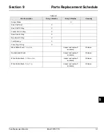
Страница 46: ...haft O Ring X Freezer Door O Ring X Draw Valve O Ring X Door Spout O Ring X Front Bearing X Prime Plug O Ring X Black Bristle Brush 1 in x 2 in Inspect and replace if necessary Minimum Double Ended Br...

Страница 47: ...9 2 PARTS REPLACEMENT SCHEDULE Model C303 C314 Parts Replacement Schedule 9 Notes...

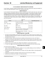
Страница 48: ...be required at time of service 2 This limited warranty is valid only if the Product is installed and all required service work on the Product is performed by an authorized Taylor distributor or servic...

Страница 49: ...rigerant other than that specified on the Product s data label will void this limited warranty 13 Any cost to replace refill or dispose of refrigerant including the cost of refrigerant 14 ANY SPECIAL...

Страница 50: ...ified proof of purchase may be required at time of service 2 This limited warranty is valid only if the Part is installed and all required service work in connection with the Part is performed by an a...

Страница 51: ...g warranty service work promptly upon arrival 9 Failure damage or repairs due to faulty installation misapplication abuse no or improper servicing unauthorized alteration or improper operation or use...

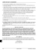
Страница 52: ...R INCIDENTAL DAMAGES INCLUDING CLAIMS FOR LOST SALES LOST PROFITS PRODUCT LOSS PROPERTY DAMAGES OR SERVICE EXPENSES ARE EXPRESSLY EXCLUDED THE EXPRESS WARRANTIES MADE IN THIS LIMITED WARRANTY MAY NOT...

Страница 53: ...11 4 LIMITED WARRANTY ON PARTS Model C303 C314 Limited Warranty on Parts 11 Notes...

Отзывы: