6-4
OPERATING PROCEDURES
Model C303 & C314
Operating Procedures
6
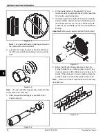
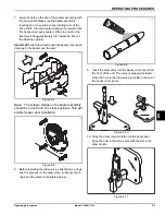
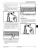
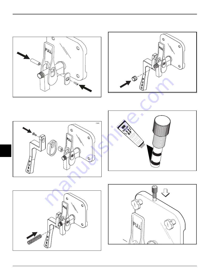
11. Slide the pivot pin through the draw handle, the draw
valve, and into the door handle slide. Secure the
assembly with the 3/8” (9.5 mm) screw.
Figure 6-12
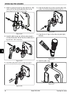
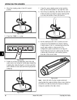
12. Install the ADA handle pin, ADA mounting adaptor,
and the ADA handle. Secure the draw handle assem-
bly with the 1” (25 mm) screw.
Figure 6-13
13. Insert the spring into the front of the door spout.
Figure 6-14
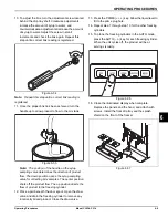
14. Place the threaded cap on the end of the draw valve
cavity. Turn the cap clockwise until it is secure.
Figure 6-15
15. Place the two O-rings on the prime plug and lightly
lubricate.
Figure 6-16
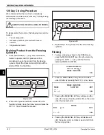
16. Install the prime plug.
Figure 6-17
11133
11446
11447
11193
11227
Содержание C303
Страница 14: ...3 4 SAFETY Model C303 C314 Safety 3 Notes...
Страница 41: ...OPERATING PROCEDURES 6 13 Model C303 C314 Operating Procedures 6...
Страница 43: ...7 2 OPERATOR CHECKLIST Model C303 C314 Operator Checklist 7 Notes...
Страница 47: ...9 2 PARTS REPLACEMENT SCHEDULE Model C303 C314 Parts Replacement Schedule 9 Notes...
Страница 53: ...11 4 LIMITED WARRANTY ON PARTS Model C303 C314 Limited Warranty on Parts 11 Notes...

