10
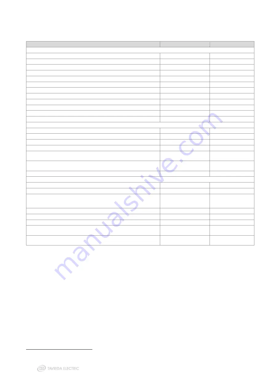
Main technical data and recloser technical parameters are presented in tables below.
Table 1
– Recloser technical parameters
Parameter
OSM15_Al_1
OSM25_Al_1
Rated data
Rated maximum voltage (Ur)
15.5 kV
27 kV
Rated short-duration powerfrequency withstand voltage (Ud), 1 min dry
50 kV
60 kV
Rated short-duration powerfrequency withstand voltage, 10s wet
45 kV
50 kV
Rated lightning impulse withstand voltage (peak) (Up)
110 kV
125
1
/ 150
2
kV
Rated continuous current (Ir)
630 A
630 A
Rated cable-charging current switching
10 A
25 A
Rated line-charging current switching
2 A
5 A
Rated short-circuit breaking current (Isc)
16 kA
12.5 kA
Rated peak withstand current (Ip)
41.6 kA
32.5 kA
Rated short-time withstand current (Ik)
16 kA
12.5 kA
Rated duration of short circuit (tk)
4 s
4 s
Rated frequency (fr)
50/60 Hz
50/60 Hz
Switching performance
Mechanical life (CO-cycles)
30 000
30 000
Operating cycles, rated current (CO-cycles)
30 000
30 000
Electrical endurance, breaking current (O-CO cycles)
Closing time, not more than
77 ms
77 ms
Opening time for overcurrent protection according to IEC 62271-111/C37.60, not
more than (at I>2xIp)
43 ms
43 ms
Clearing time for overcurrent protection according to IEC 62271-111/C37.60, not
more than (at I>2xIp)
51 ms
51 ms
Rated operating sequence
O-0.1s-CO-2s-CO-2s-CO
O-0.1s-CO-2s-CO-2s-CO
General information
Main circuit resistance
< 85 μOhm
< 95 μOhm
Weight
68 kg
72 kg
Altitude
2000 m (derating according
to ANSI C37.60 applied
above 1000 m)
2000 m (derating
according to ANSI C37.60
applied above 1000 m)
Humidity
100%, condensing
100%, condensing
Solar Radiation
≤ 1.1 kW/m²
≤ 1.1 kW/m²
Temperature Range
-
40 °C ... +55 °C
-
40 °C ... +55 °C
Type of driving mechanism
Monostable magnetic
actuator
Monostable magnetic
actuator
Pollution level
Very heavy (as per IEC
60815)
Very heavy (as per IEC
60815)
1 Across vacuum gap
2 Closed contacts
Содержание Rec15
Страница 1: ......
Страница 5: ...1 Introduction...
Страница 9: ...2 Technical Parameters...
Страница 14: ...3 Product Description...
Страница 26: ...26 Figure 25 Anti vandal housing...
Страница 27: ...4 Functionality...
Страница 56: ...5 Product Handling...
Страница 69: ...6 Installation...
Страница 81: ...7 Commissioning...
Страница 84: ...8 Operation...
Страница 99: ...99 Figure 76 Settings uploading wizard...
Страница 100: ...9 Maintenance and Troubleshooting...
Страница 114: ...114 Figure 90 Securing the trip hook shaft against rotation...
Страница 115: ...10 Product Coding...
Страница 122: ...11 Appendices...
Страница 128: ...128 Appendix 4 Recloser Control Drawings Figure 99 Dimensions of RC5_4...
Страница 131: ...131 Figure 103 Dimensions of substation recloser package Figure 104 Placement of substation recloser components in a box...
Страница 133: ...133 Figure 106 Dimensions of standard OSM mounting kit arrangement for lateral installation...
Страница 134: ...134 Figure 107 Dimensions of interface bracket...
Страница 135: ...135 Figure 108 Dimensions of OSM mounting kit with M16 pole interface front installation...
Страница 136: ...136 Figure 109 Dimensions of OSM mounting kit with M16 pole interface lateral installation...
Страница 137: ...137 Figure 110 Dimensions of OSM mounting kit with M20 pole interface front installation...
Страница 138: ...138 Figure 111 Dimensions of OSM mounting kit with M20 pole interface lateral installation...
Страница 139: ...139 Figure 112 Dimensions of OSM mounting kit for installation through the pole front installation...
Страница 140: ...140 Figure 113 Dimensions of OSM mounting kit for installation through the pole lateral installation...
Страница 149: ...149 Figure 122 Dimensions of OSM substation mounting kit...
Страница 150: ...150 Figure 123 Dimensions of RC mounting kit for around the pole installation 500 mm U profiles 450 mm M16 threaded rods...
Страница 152: ...152 Figure 125 Dimensions of RC mounting kit for through the pole installation...
Страница 153: ...153 Figure 126 Dimensions of RC substation mounting kit...
Страница 154: ...154 Figure 127 Dimensions of VT mounting kit One VT holder...
Страница 157: ...157 Figure 132 Dimensions of VT mounting kit Two VT holders two 500 mm U profiles and M16 threaded rods...
Страница 158: ...158 Figure 133 Dimensions of VT mounting kit Two VT holders two 700 mm U profiles and M20 threaded rods...
Страница 159: ...159 Figure 134 Dimensions of VT mounting kit Two VT holders four 500 mm U profiles and M16 threaded rods...
Страница 163: ...163 Appendix 8 Connectors Drawings Figure 141 Dimensions of aerial connector...
Страница 164: ...164 Figure 142 Dimensions of bird guards for aerial connector...
Страница 165: ...165 Figure 143 Dimensions of two hole NEMA connector...
Страница 166: ...166 Figure 144 Dimensions of bird guards for two hole NEMA connector...
Страница 167: ...167 Figure 145 Dimensions of four hole NEMA connector...
Страница 168: ...168 Figure 146 Dimensions of bird guards for four hole NEMA connector...
Страница 169: ...169 Figure 147 Dimensions of Burndy NEMA connector...
Страница 170: ...170 Appendix 9 Recloser Control Wiring Diagram Figure 148 RC5_4 wiring diagram...
Страница 172: ......