35
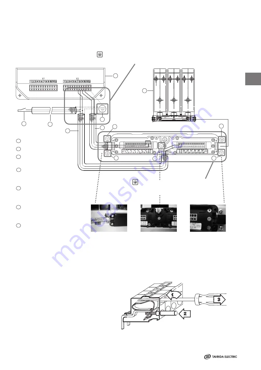
Figure 53
CM
ISM
Grounding point at CM
and at ISM
Actuator cable
Lapp Ölflex classic 110 CY
2 x 1.5 mm² (or equivalent)
2)
ISM auxiliary switch cable
1)
Lapp Ölflex classic 110 CY
2 x 1.5 mm² (or equivalent)
2)
Closing lock-out cable
1)
Lapp Ölflex classic 110 CY
2 x 1.5 mm² (or equivalent)
2)
Closing lock-out contact
(optional)
1
2
3
4
5
6
7
1)
For ISM auxiliary switch cable and
closing lock-out cable the cross section
can be chosen smaller up to 0.5 mm².
2)
The degree of coverage of the cable
shield shall be not less than 85%.
Ins tallation of Secondary Cables between ISM and CM
The installation of secondary cables between ISM and CM shall be performed regarding the subsequent connecting
diagram and indications (figure 53). These instructions are required to achieve best possible protection against
electromagnetic influence.
Unshielded parts of wires to ground point and to CM not more than 10 cm.
Grounding point as near as possible at CM.
2
1
3
3
3
3
4
5
6
7
Actuator coil
3
3
ISM position switch
Grounding points are available at and in terminal arragement of ISM.
Connections between end of cable shields and ISM-grounding points not
longer than 5 cm. Unshielded parts of wires to ISM not longer than 10 cm.
As a additional measure it is recommended to install the shielded cables
between ISM and CM in an grounded metal hose or an enclosed metal
Figure 52
The cables are fixed with a special screwdriver
supplied with every ISM and CM (Figure 48). Solid
or multi-wire cables with or without sleeves with a
cross section of 0.5 to 2.5 mm² can be connected to
the terminals. The bare ends of the cables shall be 8
to 9 mm.
1- Insert screwdriver into the rectangular hole and
press the contact spring.
2- Insert wire into the corresponding round hole.
3- Remove the screwdriver and pull the wire slightly
to check the reliability connection
3
Содержание ISM Shell_2 Series
Страница 1: ...ISM Shell_2 Series Vacuum Circuit Breaker 15kV 29kA 2000A Applications Manual MAN5002239 Revision 4...
Страница 2: ...2...
Страница 6: ...6 1 THIS PAGE INTENTIONALLY LEFT BLANK...
Страница 7: ...7 Introduction 1...
Страница 12: ...12 1 THIS PAGE INTENTIONALLY LEFT BLANK...
Страница 13: ...13 Receiving Handling and Storage 2...
Страница 19: ...19 Ins tallation 3...
Страница 36: ...36 3 THIS PAGE INTENTIONALLY LEFT BLANK...
Страница 37: ...37 Switching and Control Functions 4...
Страница 41: ...41 Commiss ioning Maintenance 5...
Страница 44: ...44 5 THIS PAGE INTENTIONALLY LEFT BLANK...
Страница 45: ...45 Signalling 6...
Страница 49: ...49 Special Applications Fast Switching 6...
Страница 53: ...53 Product Line 7...
Страница 55: ...55 Dimens ions and Weights 8...
Страница 61: ...61 8 Mating part with interlocking lever Interlockingshaftwithmountedinterlockinglever...
Страница 62: ...62 Circuit Diagrams 9...
Страница 63: ...63 ISM15_Shell_2 with CM_1501_01 9...
Страница 64: ...64 ISM15_Shell_2 with CM_16_1 9...
Страница 65: ...65 9 THIS PAGE INTENTIONALLY LEFT BLANK...
Страница 66: ...66 Technical Data 10...
Страница 71: ...71 10 THIS PAGE INTENTIONALLY LEFT BLANK...
Страница 72: ...72 Regulations and Ambient Conditions 11...
Страница 74: ...74 Legal Information 12...
Страница 77: ...77 12 THIS PAGE INTENTIONALLY LEFT BLANK...
Страница 79: ...79 Date 12...
Страница 80: ...80 Date 12...
Страница 81: ...81 Date 12...
Страница 82: ...82 THIS PAGE INTENTIONALLY LEFT BLANK...


