background image

15

3. Basic Setup

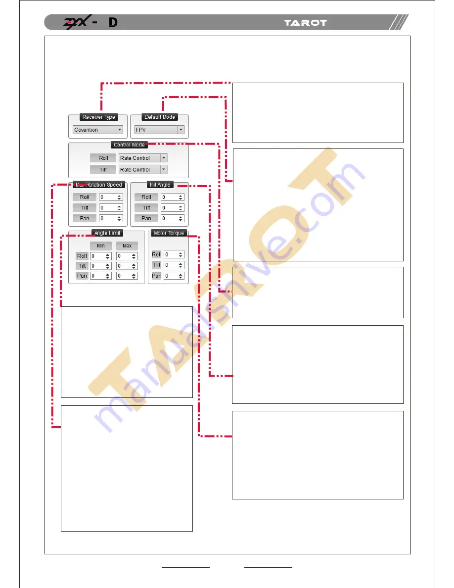
1.Receiver Unconnected: set gimbal mode in Default 

   Mode of assistant software.

2. Receiver Connected: set gimbal mode in MODE 

   channel of the receiver.


FPV Mode

: The direction of the gimbal and directions 

   (roll, tilt and pan) of the multi-rotor are the same.


PFMode

:The head of the multi-rotor and the gimbal 

   are in the same direction.


AL Mode

:The gimbal keeps a xed angle.

Init Angle stands for the initial angle of each direction 
after the gimbal has been powered up. For instance, 
if you want the tilt direction of the camera is on -45 
degree, you should enter -45 on the corresponding box. 
Angle Range of Roll:-25°~25°
Angle Range of Tilt:-120°~15°
Angle Range of Pan:-125°~125°
Please press “ENTER” button after modifying the parameters.

Angle Range of Rotation on each Direction 
of the Gimbal.
If the gimbal rotates to or over the extreme 
value, it would stop rotating until the value 
goes within the range.
The Extreme Range of Roll:-25°~25°
The Extreme Range of Tilt:-120°~15
The Extreme Range of Pan:-125°~125°
Please press “ENTER” button after 
modifying the parameters.

The maximum rotation speed the 
gimbal can reach.
      When pushing sticks to the maximum but 
the rotation speed is lower, you could 
increase the value of Max Rotation Speed 
to enhance the rotation speed;
      When pushing sticks gradually but the 
rotation speed is too fast, you could 
decrease the value to slow down the speed.
      Max Rotation Speed Range of 
ROLL: 0~200(degree/sec)
      Max Rotation Speed Range of 
TILT:0~200(degree/sec)
     Max Rotation Speed Range of 
PAN:0~200(degree/sec)
     Please press “ENTER” button after 
modifying the parameters.

Methods to Connect the Receiver:
Common Receiver

: respectively connect to CH1-CH7 

channel through 3P cables.

SBUS Receiver

: Connect to CH7 channel 

through a 3P cable.

Satellite Receiver

: connect to the satellite 

receiver DSM port.

Methods to control gimbal rotation by Tx (roll and tilt only):

Rate Mode

: The position of the stick is corresponding to 

the rotate speed of the gimbal.

Angle Mode

: The position of the stick is corresponding to 

the angle of the gimbal.

It relates to the response speed of the gimbal.When it 
becomes too small, the stabilitydeteriorates. When it 
turns too large, self-oscillation occurs.

Methods to adjust

: if vibration occurs, please decrease 

the parameters until it disappears.

Input Range: 0~200

Please press “ENTER” button after modifying 
the parameters.

Attention: it has been adjusted to an appropriate value 
before leaving factory. If vibrations do not occur, please 
do not modify this value.

ASSEMBLY SECTION

5

Содержание ZYX-5D

Страница 1: ...nual Thanks for your purchase of Tarot professional aerial photography products To ensure your success with this product we would like to introduce the foll owing information and important notes hope...

Страница 2: ...rol 8 4 Video Signal Transmission 9 5 Gimbal Controller Connection 10 6 Gimbal Working Mode 11 12 C Flight Test 13 D ZYX 5D Assistant Software 14 1 Drive PC Assistant Software Installation and Setup 1...

Страница 3: ...o avoid malfunctions of internal wirings or perform ance degradations In order to ensure the safety of ight control system after powering up we recommend you to remove all the propellers and usenon po...

Страница 4: ...module specialized servo drive module this gimbal is able to support three working modes including Attitude Lock AL mode Pan Follow PF mode and First Person View FPV mode Pan Motor Drive Module Indic...

Страница 5: ...to Flight Control Cable USB Cable 1 Canon 5D MARK III Camera 1 Canon EF 17 40mm f 4L USM Lens 1 Multi rotor 1 RX TX Cable 5 USB module 1 ASSEMBLY SECTION 5 With unique internal wiring design built in...

Страница 6: ...f timer remotecontrol or 10 sec self timer remote control TIPs In Manual Exposure please set the ISO to Auto Please adjust the shutter speed between 1 100 and 1 30 seconds With manual exposure please...

Страница 7: ...into the gimbal Tighten up the camera mounting screw Tighten up the lens retaining plate screw Attention Please screw down both screws otherwise vibrations might occur ASSEMBLY SECTION 5 Camera Mount...

Страница 8: ...during mounting We have correctly adjusted the center of gravity of the gimbal Please DO NOT change it based on your preference The controller module with pin port side should face to the head of the...

Страница 9: ...sition 2 Position 1 Position 2 Position 3 Take a photo Start recording Centered no action centered no action Take another photo Stop recording ASSEMBLY SECTION 5 ZYX 5D gimbal is able to transfer the...

Страница 10: ...t to control the camera through a 2 position switch Please set your transmitter and observe the cursor of PVC channel in the assistant software Either taking photos or recording can be applied in this...

Страница 11: ...8 RX TX GND SIGNAL 5V GND 5 Gimbal Controller Connection XT60 10 ASSEMBLY SECTION 5 Pan Motor Drive Module Indicator Av Port Gimbal Controller Upgrade Port Gimbal Cotroller Indicator Pan Motor Drive M...

Страница 12: ...software If binding is not successful in DSM2 1 or DSMX 1 please choose DSM2 2 or DSMX 2 to bind Connect the wireless video transmission module to AV port through a 3 5mm AV cable Gimbal can work with...

Страница 13: ...Working Mode setup Position 1 and Position 3 can be exchanged Choose a three positioned switch Mode ASSEMBLY SECTION 5 When the MODE port is unconnected the gimbal can only work in the DEFAULT mode Mo...

Страница 14: ...check the rotation direction in ROLL PITCH and PAN axis TIPs Before ight test please ensure 1 Correctly mount the camera into the gimbaland the gimbal onto the landing gear 2 All the wirings are corr...

Страница 15: ...ree axis gimbal could support the camera to stabilize its positions on the roll tilt and pan axis You could adjust receiver type working mode angle range and other options in the assistant software Fi...

Страница 16: ...tation speed is lower you could increase the value of Max Rotation Speed to enhance the rotation speed When pushing sticks gradually but the rotation speed is too fast you could decrease the value to...

Страница 17: ...ned channel to map to PVC channel 2 Toggle the switch once the camera would take a photo or start recording PI Mode switch to this mode for one time the camera would take a photo VI Mode switch to thi...

Страница 18: ...ocedures and send your concerns or problems through the feedback on the top right corner of the assistant software 1 Power up the gimbal and correctly connect to the assistant software 2 Choose a corr...

Страница 19: ...oo large 2 Flight control module is unconnected 1 Calibrate sensors 2 Connect to ight control module 1 Error of sensors is too large 2 Tx is not centered 1 Calibrate sensors 2 Center the Tx 1 The came...

Страница 20: ...ported Camera Supported Lens Assistant Software Supporting Platform Dimensions Weight 3S 6S Li 11V 26V 120mA 25V 180mA 12V 4000mA 25V 8000mA 12V 20 50 215x235x231mm TILT 200 deg sec ROLL 200 deg sec P...

Страница 21: ...ler Upgrading Port Video Output Port Satellite Receiver Port Common Receiver Input Port 1 Common Receiver Input Port 2 Common Receiver Input Port 3 Common Receiver Input Port 4 Common Receiver Input P...

Страница 22: ...shes slowly BLUE light ashes quickly Self check process status Self check status Self check process fails Self check fails Work properly Work properly Line fault or some module is upgrading Bind with...

Отзывы: