TAILY AUTOMATION CNC-210A Скачать руководство пользователя страница 9

 CNC-210A Series  H6681 User manual


Page 

9

 of 

20


έᚊ࿪ཝҋજ̼ѣࢨ̳Φ


TAILY AUTOMATION CO.,LTD. 
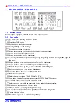
 

7. CONFIGURATION 

SETTING 

CNC-210A is a multi-purpose design, to meet various requirements; additional settings are 

configured to provide flexibility for additional applications. 

In the READY mode, press the following keys combination as


section 

[7.1. ~7.10],

 the DATA 

DISPLAY will show corresponding setting value. If no change is necessary, press the

key get 

back to READY mode. Or press

key


to get into change mode, then the parameter can be 

changed by pressing the numerical key followed by the

key. 

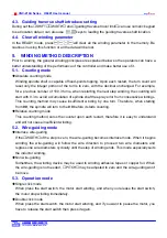
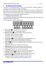
7.1.  Winding mode selection


In this function the STEP display and the DATA display will shows eight digits, representing eight 

winding mode selections respectively. 

Press numerical keys as below to set each digit.   

1

2

3

4

5

6

7

8


Moving speed

The guiding traverse moving speed. 

0

 represents high speed

; 1

 represents low speed. 


Moving increment

The travel increment of the guiding traverse. 

represents 0.01mm (4 mm per revolution). 

represent 0.02mm (8 mm per revolution).   

4

 represent 0.04mm(16 mm per revolution. 


Counting mode

Select the counting mode of the winding spindle shaft.           

0

 represents with zero point and using absolute counting mode.

represents without zero point and using relative counting mode.

 Edge slow

Slow down the winding speed before the guiding traverse reach to the two 

edges of the width. 

0

 represents not slow down

; 1 

represents to slow down. 


Braking mode

Select the braking mode of the winding spindle.   

0

 represents single brake mode

; 1 

represents double brake mode. 

 Counting unit

Select 0.1 or 1 turns as your count unit.


0

 represents 

0

.

1

(0.0 to 9999.9 turns); 

represents

 1

(0 to 99999 turns). 


Guiding traverse unit

Select the basic unit of guiding traverse.


0

 represents 

mm;


represents

 inch

 (must using lead screw in imperial). 

 Operation mode

Select operation mode for the START switch. 

0

 represents Single click mode

;


represents


Double click mode. 

The

key on the front panel always as the Double click mode. 

Содержание CNC-210A

Страница 1: ...OMATION CO LTD 1 INTRODUCTION 2 2 MAIN FEATURES 2 3 FRONT PANEL DESCRIPTION 3 4 PROGRAMMING WINGING PARAMETER 5 5 WINDING METHOD DESCRIPTION 6 6 WINDING EXECUTION 8 7 CONFIGURATION SETTING 9 8 INSTALL...

Страница 2: ...p DC motor in directly Drive two phases 2A STEP motor in directly CNC 210AE External connect winding spindles motor driver Drive two phases 2A stepper motor in directly Or external connect guiding tra...

Страница 3: ...edge of the width Select whether to have auto positioning function for each step Select whether to have auto starting function for each step Reduce step number by one or reduce PIECE COUNTER by one D...

Страница 4: ...means winding operation is over speeding guiding traverse and winding spindle shaft are out of synchronization LAN Lit means currently are communicating with network FINISH Will lit when reaching the...

Страница 5: ...y pressing the numerical keys followed by the key After that the STEP number will automatically increase by one to continue set the SHIFT for next step When the STEP number is larger then the END STEP...

Страница 6: ...spindle shaft free play error from consecutive windings This counting method may cause insufficient winding by one turn Therefore when starting from 0 9 the spindle will turn to the 0 0 before it star...

Страница 7: ...and start winding without press key work with and keys 5 5 How to set winding turns accurately Preset method Set the E SLOW to zero first and then set the TURNS to the desired number Set proper param...

Страница 8: ...position 6 3 Winding speed RPM display Pressing key will cause the PIECE COUNT DISPLAY to display the spindle shaft RPM without interrupting the counting Pressing again will change the PIECE COUNT DI...

Страница 9: ...ng increment The travel increment of the guiding traverse 1 represents 0 01mm 4 mm per revolution 2 represent 0 02mm 8 mm per revolution 4 represent 0 04mm 16 mm per revolution Counting mode Select th...

Страница 10: ...e READY mode Setting range 000 00 999 99 999 99 Means no limit 7 5 Fixed location To set how often must be correct the guiding traverse location Each time when finish this number of product pieces the...

Страница 11: ...to the section 7 2 station numbers The communication bus wiring diagram as below CNC 210AS CNC 210AS CNC 210AS RS 485 CONNECTION BOX COOMUNICATION CABLE 6P4C EARTH TERMINATOR RESISTOR 47 100ohm RS 485...

Страница 12: ...oller Make sure the machine and controllers are properly grounded Make sure that the leads and connectors are connected correctly Normally operate under 10 40 environment over 40 should perform under...

Страница 13: ...e Output 0V DIR PUS 5V Operate Switches 1 2 3 4 a b 1 2 3 4 a b IP1 IP2 IP3 IP4 COM OP1 OP2 OP3 OP4 24V AUX I O CN6 IP5 IP6 8 3 Wiring diagram for CNC 210AS GND M A A B B 11 12 AC AC BK BK A A B B COM...

Страница 14: ...R TR RS 485 Pulse Output Home Sensor Turn Counter AUX I O AC Output 0V DIR PUS 5V AC GND AC A STEP Motor Motor Motor Driver AC Output External connect STEP Motor driver 11 12 AC AC BK BK A A B B GND M...

Страница 15: ...nding parameter H S L S in 20 then press to change the DISPLAY shows RPM Then press key to start winding 2 Rotate IR potentiometer to make it in same speed during the winding spindle shaft in full loa...

Страница 16: ...adjust 1 Set the winding parameter H S L S in 99 and press key to change the DISPLAY shows RPM Then press key to start winding 2 Rotate V out potentiometer to make the winding speed RPM as you want T...

Страница 17: ...eriodically maintain Please periodically clean up the controller inner accumulate dust and dopants Please periodically check the wire connection between controller and machine if have loose or bad con...

Страница 18: ...de the user in understanding different fault condition and their general troubleshooting procedures and with their possible solutions Do not connect or disconnect wires and connectors while power is a...

Страница 19: ...value b Check configurations TRAVEL LIMIT setting value 8 Display shows Err 3 then reset and get into READY mode Check winding parameters SHIFT and WIDTH setting value Replace HOME SENSOR 9 Display sh...

Страница 20: ...CNC 210A Series H6681 User manual Page 20 of 20 TAILY AUTOMATION CO LTD Agency...

Отзывы: