Fig. 20: Interface plate on the rear of the PILOT 219 PC (depending on the
configuration)
4.
Connect up all the cables between the interface plate and the
equipment rack adapter.
5.
Tighten the screws on the mains plug.
6.
Fasten the PILOT 219 PC to the equipment rack adapter using the
four M5 x 16 screws.
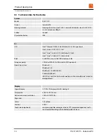
You will find a view of the backplane in section
Ä
Chapter 3.4
“Dimensions” on page 16
.
1512
222
734,82
222
1160
Fig. 21: Screw connections on the equipment rack adapter
ð
The PILOT 219 PC is now mounted.
Starting up
Mounting the device
PILOT 219 PC - Industrial PC
26
Содержание PILOT 219
Страница 4: ...Table of contents PILOT 219 PC Industrial PC 4 ...
Страница 6: ...General information Copyright notice PILOT 219 PC Industrial PC 6 ...
Страница 10: ...Safety Important safety notes PILOT 219 PC Industrial PC 10 ...
Страница 22: ...Product description Conformity PILOT 219 PC Industrial PC 22 ...
Страница 34: ...Repairs PILOT 219 PC Industrial PC 34 ...
Страница 38: ...Storage Storing the device PILOT 219 PC Industrial PC 38 ...
Страница 40: ...Packaging and transport Transporting the device PILOT 219 PC Industrial PC 40 ...
Страница 42: ...Disposal PILOT 219 PC Industrial PC 42 ...


