background image


48 

9.  Appendices: How to Use the Project File 

 
This section explains the procedure for using the following project file. The project file contains 
the contents described in "7.3. Controller Setup". 
Obtain the latest version of the Project File from OMRON Corporation. 
 

Name 

Filename 

Version 

Sysmac Studio Compact 

Project File (Extension: 

csm2) 

OMRON_F430_NX_EIP_V100.csm2  Ver.1.00 
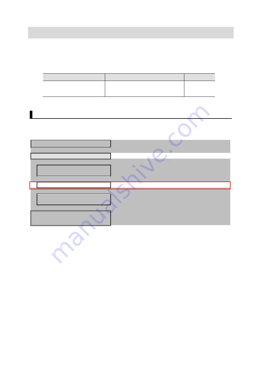


9.1.  Operation Flow 

The following steps are for how to use the project file to set up EtherNet/IP Tag Data Links. 
Refer to each section except “9.2.1. Load the Project File” enclosed in the red frame. 
 

7.2. Smart Camera Settings 

  Setting up the Smart camera. 


9.2. Controller Setup 

  Set up the controller using the Project File. 


  7.3.1. Parameter Settings 

  Launch Sysmac Studio and set the IP address of the 

controller. 


  9.2.1. Load the Project File 

  Load the Project File in to Sysmac Studio. 


  7.3.7. Transfer the Project Data 

  Connect online and transfer the connection settings 

and the project data to Controller. 


7.4. Confirm EtherNet/IP 

Communications 

  Confirm that the EtherNet/IP tag data links operate 

normally. 


Содержание Omron F430-F Series

Страница 1: ...Z441 E 01 Machine Automation Controller NX Series EtherNet IPTM Connection Guide Smart camera F430 F Series...

Страница 2: ...f Microsoft Corporation in the USA and other countries ODVA EtherNet IPTM are trademarks of ODVA Sysmac and SYSMAC are trademarks or registered trademarks of OMRON Corporation in Japan and other count...

Страница 3: ...to Use for Tag Data Links 10 6 3 Global Variables 12 6 4 Tag Set 16 6 5 Tag Data Link Table 16 7 EtherNet IP Connection Procedure 17 7 1 Operation Flow 17 7 2 Smart Camera Setup 18 7 3 Controller Setu...

Страница 4: ...eries CPU Unit User s Hardware Manual W593 NX Series NX Series NX102 CPU Unit Hardware User s Manual W578 NX Series NX Series NX1P2 CPU Unit Hardware User s Manual W501 NJ NX Series NJ NX Series CPU U...

Страница 5: ...ata Link A Tag data link is a function to exchange data for each tag cyclically between controllers or between a controller and other device type on an EtherNet IP network Connection A connection is a...

Страница 6: ...formation contained in this document is current as of January 2020 It is subject to change for improvement without notice The following notations are used in this document Indicates a potentially haza...

Страница 7: ...Connection Procedure to understand setting methods and key points to operate EtherNet IP tag data links Note Settings described in 7 3 Controller Setup are made in advance in the Sysmac Studio project...

Страница 8: ...ocedure please refer to the instruction manual of the product or contact OMRON Note In this document from among the above target devices connection confirmation is performed using the devices listed i...

Страница 9: ...1 29 OMRON Sysmac Studio Project File OMRON_F430_NX_EIP_ V100 csm2 Ver 1 00 Computer OS Windows 10 LAN cable STP shielded twisted pair cable of Ethernet category 5 or higher OMRON Smart camera F430 F...

Страница 10: ...and after In that case use the equivalent procedures described in this document by referring to the Sysmac Studio Version 1 Operation Manual Cat No W504 Note Refer to Industrial Switching Hub W4S1 Ser...

Страница 11: ...255 0 0 default Gateway 0 0 0 0 Default As needed IP Address Mode Fixed EtherNet IP Enabled KeepAlive Enabled default For the use cases in this document setting the gateway is unnecessary because the...

Страница 12: ...3 String length string103 STRING 28 GDS string103 string104_length DINT GDS string104 String length string104 STRING 28 GDS string104 1 For more detailed GDS information please click on the Omron Micr...

Страница 13: ...l variable below is set to Project file Variable Network Publish Data type Usage EIPOutput Output S_EIPOutput For Output Area data links EIPInput Input S_EIPInput For Input Area data links EIPOutput S...

Страница 14: ...tion GO ONLINE Starts all executed Inspections GO OFFLINE Stops all inspections RESET ERROR Reset Status Register ERROR RESET COUNT Resets the Count for all inspections EXE CMD Executes the command sp...

Страница 15: ...sult Status of Inspection 1 If the inspection passed it will be 1 It is valid only when DataValid becomes High DATA VALID When Inspection 1 completes this bit becomes High The PLC should set RESET DV...

Страница 16: ...15...

Страница 17: ...size byte EIPInput 320 IN No Global Variable Name Tag Name Data size byte 1 EIPInput 320 6 5 Tag Data Link Table The content of tag data link table settings connection settings is shown below The val...

Страница 18: ...ters for the Smart camera 7 3 Controller Setup Set up the Controller 7 3 1 Set IP Address Launch Sysmac Studio and set the IP address of the controller 7 3 2 Target Device Registration Register the ta...

Страница 19: ...era to the switching hub with the Ethernet cable Connect the I O cable to I O connector and turn on the 24VDC power supply This document is only for verification of the power supply wiring of the I O...

Страница 20: ...the Windows Start menu select Control Panel Network and Internet Network and Sharing Center 2 Click on Local Area Connection The Local Area Connection Status Dialog Box is displayed Click Properties...

Страница 21: ...espective IP Addresses on the PC and on the F430 smart camera set correctly Refer to 4 for setting the IP Address of the PC Do a hardware reset of the F430 When turning the power on press and hold the...

Страница 22: ...Locate Shape tool the text string read by the OCR tool and character text decoded from a 2D Code using Ethernet IP communications 10 Select the Camera Tools and set the Trigger to Sensor 1 1 1 Select...

Страница 23: ...he second icon Output String and set it to EIP Input String 1 13 Select Decode click the first icon Status and set it to bool1 of EIP input 14 Select Decode click the second icon Decoded Text and set...

Страница 24: ...set correctly 16 Go to Run view and download the job to smart camera 17 The download is complete when you can successfully transition to the Run screen 7 3 Controller Setup Set up the Controller 7 3...

Страница 25: ...rtup select the option to start 3 Sysmac Studio starts Click New Project 4 The Project Properties Screen is displayed In this document New Project is used as the project name Select the device to use...

Страница 26: ...ter of the screen displayed Output Tab Page Build Tab Page 7 Double click Built in EtherNet IP Port Settings under Configurations and Setup Controller Setup in the Multiview Explorer 8 The Built in Et...

Страница 27: ...n successfully installed the EDS can be found in C OMRON Vscape Firmware eds F430 1 Select EtherNet IP Connection Settings from the Tools Menu 2 Double click Built in EtherNet IP Port Settings 3 Right...

Страница 28: ...ibrary Dialog Box is displayed Select Install 5 Select the EDS file you downloaded and then click on Open O 6 Verify that Microscan Systems Inc Vendor Specific Machine Vision Smart Camera F430 F has b...

Страница 29: ...herNet IP Connection Settings 2 In the Edit Pane the EtherNet IP Device List tab is displayed With Built in EtherNet IP Port Settings selected right click the mouse and select Edit from the menu 3 The...

Страница 30: ...Address enter 192 168 188 2 Click on the Model Name and Revision fields and select the following from their pulldown menus Model F430 F Revision 1 6 Confirm your selection and click Add 7 192 168 188...

Страница 31: ...and output assemblies refer to Smart Camera F430 F Series User Manual for Communications Settings Z444 1 Double click Data Types under Programming Data in the Multiview Explorer 2 The Data type tab i...

Страница 32: ...5 As described in steps 3 to 4 create new Data Types and Members Here we create Data types for the Output Assembly that controls the F430 such as bits for trigger input For details of the content on t...

Страница 33: ...elect Output 8 Confirm this is entered correctly and then right click on the mouse to select Create New from the menu 9 As in step 7 enter the following data in the Create New Area Name EIPInput Data...

Страница 34: ...iables set in this section are displayed Select EIPOutput S_EIPOutput is added Data Type is automatically set No value needs to be entered 12 Using the same procedure as in step 11 add all the variabl...

Страница 35: ...menu 3 Here you can enter the New Tag Set Name Select the newly added Input Area Enter EIPInput 4 With EIPInput selected right click the mouse and select Create New Tag from the menu In EIPInput you...

Страница 36: ...the menu 6 Here you can enter the New Tag Set Name Following the same procedure described in Step 3 enter EIPOutput 7 Using the same procedures described in Step 4 add the Global variables as Tags in...

Страница 37: ...lt in EtherNet IP port Connection Settings tab select Connection 2 Right click in Connection to select Create New Connection from the menu 3 Here you can enter the new connection Select the newly adde...

Страница 38: ...umber all the possible Assembly Numbers beginning with that digit will be displayed Select the Assembly Number In the same manner set the Target Variable for Output 7 Now click on Originator Variable...

Страница 39: ...t Before transferring project data check the safety of the transfer destination slave 1 Turn power ON to the Controller switching hub and smart camera 2 From the Main Menu in Sysmac Studio select Proj...

Страница 40: ...9 From the Menu Bar select Controller Online A confirmation dialog will be displayed Confirm the information and click Yes The dialog that is displayed differs depending on the status of the controll...

Страница 41: ...connection settings built in port and Unit is unchecked Click the Transfer to Controller Button Executing Transfer to Controller transfers the data of Sysmac Studio to the controller and checks that...

Страница 42: ...s check the physical connections and perform the steps again from Step 1 15 In Controller Status confirm that there is a Green light for ERR ALM and that the Mode is Program Mode Precautions for Corre...

Страница 43: ...42...

Страница 44: ...normal operation NET RUN Lit Green NET ERR OFF LINK ACT Blinking Yellow Blinking while sending and receiving packets 2 Verify the LEDs on the smart camera Below are the LED indicators for normal opera...

Страница 45: ...e Status column is displaying 00 0000 7 Select the Tag Status tab Verify that all the Tags are listed under Tag Name and that there is a blue dot next to them or depending on the version of software b...

Страница 46: ...ly confirm safety before you change the values of variables on a Watch Tab Page when the Sysmac Studio is online with the CPU Unit 1 From Menu Bar in Sysmac Studio select View Watch Tab Page 2 Select...

Страница 47: ...lected on the AutoVision screen 6 Launch Data Navigator and check the details of the measured values 7 The measured values confirmed in Step 6 are reflected for each variable of EIPInput 8 Initializin...

Страница 48: ...alize the CPU Unit Before initialization put the controller in Program Mode and select Controller Clear All Memory from the Sysmac Studio menu bar Clear All Memory dialog is displayed confirm the cont...

Страница 49: ...project file to set up EtherNet IP Tag Data Links Refer to each section except 9 2 1 Load the Project File enclosed in the red frame 7 2 Smart Camera Settings Setting up the Smart camera 9 2 Controll...

Страница 50: ...ct file and click Open Obtain the latest version of the project file from the OMRON Corporation website t 3 The New Project dialog will be displayed Confirm the contents and click No 4 The OMRON_F430_...

Страница 51: ...ller Change Device 6 The Change Device Dialog Box is displayed Confirm that the Device and Version set to use are as shown in the figure on the right Click Cancel If the settings are different select...

Страница 52: ...51 10 Revision History Revision Symbol Revised year and date Revised Page and Reason 01 April 2022 First Publication...

Страница 53: ......

Страница 54: ...ates IL 60169 U S A Tel 1 847 843 7900 Fax 1 847 843 7787 Regional Headquarters OMRON EUROPE B V Wegalaan 67 69 2132 JD Hoofddorp The Netherlands Tel 31 2356 81 300 Fax 31 2356 81 388 Contact www ia o...

Отзывы: