background image


6


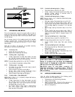
4)  Once the current has stabilized, a reading should be 

taken and the anticipator adjusted to that value.  If 
longer heating cycles are desired, the anticipator can 
be set to a higher value 


2.5.2. 

Ducts and filters 


The ducts must be sized such a way as to accommodate the 
specified airflow and the available static pressure.  Refer to the 
applicable local and/or national installation codes. 
 
Insulate the ducts that lead through non-heated areas.  Use 
flexible supply and return air connectors to avoid the 
transmission of vibration.  To make the unit run even quieter, 
the installer should: 
 

1)  Use two elbows between each outlet and the supply 

and return air plenum; 

2)  Cover the vertical sections of the supply and return air 

duct with soundproofing material; 

3)  Use baffles in short radius elbows; 
4)  Use flexible hangers to suspend the ducts. 

 
The 

SUPREME

 furnace is equipped with a filter frame for the 

blower compartment.  It must be installed on the outside of one 
of the three sides or the bottom of the furnace.  Once the 
location of the installation has been determined, use the four 
square knockouts for ease of cutting the opening. 
 
A heat pump or an air conditioner can be added to this furnace, 
in either the supply or return air duct.  Carefully follow the 
instructions provided with these appliances to ensure proper 
installation and hook-up to the electric furnace.  Refrigerant and 
drainage pipes must in no way hinder access to the furnace 
panels. 


2.6  SUPPLY AIR ADJUSTMENTS AND 

OTHER BLOWER SETTINGS


Fan Control Board taps are used by the installer to configure a 
system.  The ECM motor uses the selected taps to modify its 
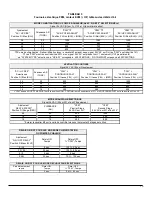
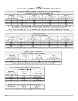
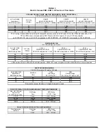
operation to a pre-programmed table of airflows (Refer to Table 
3 and Table 4). Airflows are based on system size or mode of 
operation and those airflows are modified in response to 
thermostat inputs. 
 
FEM electric furnace must be configured to operate properly 
with system components with which it is installed.  To 
successfully configure a basic system (see information printed 
on circuit board label located next to select pins), move the 6 
select wires to the pins which match the components used. 
(Refer to Figure 4 below) 

Figure 4 

Fan Control Board 


2.6.1. 

HEAT KW/CFM adjustment 


Installer must verify (factory set) the electric heat airflow 
adjustment required for kW size heater installed. 
 
The select pins are marked 23, 20, 18, 15 (for ½ HP ECM motor 
unit) and 27, 23, 20, 18 (for 1.0 HP ECM motor unit). Refer to 
the unit wiring diagram and select the pin for the heater size 
being used (Refer to Figures 4 and 9). 
 
The airflow must be large enough for safe and continuous 
operation. (Refer to Table 3 and 4 for airflow delivery CFM). 


2.6.2. 

AC/HP size 


Select System Size Installed 


The factory setting for air conditioner or heat pump size is the 
largest outdoor unit that can be used with the furnace.  Installer 
needs to select air conditioner or heat pump size to ensure that 
airflow delivered falls within proper range for the size unit 
installed. 
 
The select pins are marked 036, 030, 024, 018 for furnace 
equipped with ½ HP ECM motor and 060, 048, 042, 036 for 
furnace equipped with 1.0 HP ECM motor.  Refer to the unit 
wiring diagram and select the pin for the outdoor unit size being 
used (Refer to Figures 4 and 9). 

Содержание FEM15-E230V1M-A

Страница 1: ...on UTC Canada Division ICP 3400 boulevard Industriel Sherbrooke Québec Canada J1L 1V8 2008 04 14 X40152 Rev A DNS 0981 Rev A MULTI POSITION MOTEUR VITESSE VARIABLE INSTALLATEUR TECHNICIEN UTILISER LES RENSEIGNEMENTS DANS CE MANUEL POUR L INSTALLATION ET L ENTRETIEN DE L APPAREIL ET GARDER LE DOCUMENT PRÈS DE L UNITÉ POUR RÉFÉRENCES ULTÉRIEURES PROPRIÉTAIRE S V P GARDEZ CE MANUEL PRÈS DE L UNITÉ PO...

Страница 2: ...D AIR 10 4 ENTRETIEN 10 4 1 FILTRE À AIR 11 4 2 LUBRIFICATION DU MOTEUR 11 5 INFORMATION 11 TABLEAUX ET FIGURES FIGURE 1 CONFIGURATION DÉBIT ASCENDANT 4 FIGURE 2 CONFIGURATION DÉBIT DESCENDANT 4 FIGURE 3 CONFIGURATION DÉBIT HORIZONTAL 5 FIGURE 4 CARTE DE CONTRÔLE DU VENTILATEUR 6 FIGURE 5 RACCORDEMENT D UN HUMIDIFICATEUR 8 FIGURE 6 RACCORDEMENT D UN HUMIDIFICATEUR 8 FIGURE 7 RACCORDEMENT D UN FILT...

Страница 3: ...nationaux qui s appliquent Les renseignements contenus dans ce manuel s adressent à un technicien qualifié expérimenté dans ce type de travail au courant des précautions à prendre des règles de sécurité à respecter et muni des outils appropriés ainsi que des instruments de vérification adéquats Ne pas se conformer aux règles de sécurité énoncées dans ce manuel pourrait entraîner des dommages corpo...

Страница 4: ... un dégagement de 0 pouce par rapport aux matériaux combustibles Pour les fournaises d une puissance de 23 kW et plus les conduits d alimentation en air doivent être installés avec un dégagement de 1 pouce par rapport aux matériaux combustibles pour les 36 premiers pouces de conduits Pour l excédant ce dégagement peut être réduit à 0 pouce Pour les unités de 23 kW et plus installées en débit desce...

Страница 5: ... Un connecteur de mise à la terre est inclus dans la boîte de contrôle pour effectuer cette connexion Si vous remplacez des fils d origine de l appareil de chauffage central utilisez seulement du fil de cuivre résistant à la même température que les fils d origine 2 5 INSTALLATION DU THERMOSTAT L installation d un thermostat de contrôle de la température de l espace à chauffer est obligatoire Suiv...

Страница 6: ... les directives accompagnant les appareils afin de faire en sorte que ceux ci soient bien installés et raccordés à la fournaise électrique On notera que les tuyauteries du réfrigérant et de vidange ne devraient aucunement nuire à l enlèvement des panneaux d accès de la fournaise 2 6 AJUSTEMENT DES DÉBITS D AIR L installateur configure le système avec les terminaux situés sur la carte de contrôle d...

Страница 7: ...orer le fonctionnement du système se référer aux figures 4 et 9 Les choix de réglage sont les suivants 1 0 90 Aucun délai ON pour la mise en marche et 90 secondes de délai OFF avant l arrêt à un débit de 100 réglage par défaut 2 30 90 30 secondes de délai ON pour la mise en marche et 90 secondes de délai OFF avant l arrêt à un débit de 100 Réglage utile si l on désire laisser réchauffer refroidir ...

Страница 8: ... 24 VAC quand un signal à G venant du thermostat est présent Se référer à la figure 7 Figure 7 2 7 3 Capacité de déshumidification avec connexion à un humidistat standard DNS 1154 Rev A Les capacités latentes des systèmes associés à cette unité sont supérieures à celles des systèmes ordinaires Si une capacité latente élevée est une condition de l application la carte de contrôle est munie d une bo...

Страница 9: ...uit R vers G Ventilation et débit d air continus 3 3 2 Mode de climatisation Thermostat un stage Température intérieure supérieure au point de consigne et taux d humidité inférieur au point de consigne Le thermostat ferme les circuits R vers G R vers Y Y2 et R vers O REMARQUE Ne pas utiliser la borne Y1 sur le système à un seul stage La fournaise fournit le débit d air de climatisation requis pour...

Страница 10: ...m de retour d air 3 Mesurer la température de l air au plus large embranchement sortant du plénum d alimentation en air situé juste en dehors de la ligne de radiation provenant de l échangeur de chaleur une distance de 0 3 m 12 du plénum devrait être suffisante 4 Calculer la hausse de température en soustrayant la température de l air d alimentation moins la température de l air de retour Si la ha...

Страница 11: ...la fournaise ne chauffe pas couper l alimentation électrique et appeler un technicien qualifié 4 2 LUBRIFICATION DU MOTEUR Ne pas lubrifier le moteur du ventilateur puisqu il est lubrifié de façon permanente Lors d un appel pour le service d entretien ou pour commander une pièce de remplacement spécifier le numéro de modèle et le numéro de série de votre appareil 5 INFORMATION Modèle Numéro de sér...

Страница 12: ...12 FIGURE 9 Diagramme électrique ...

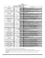
Страница 13: ...atisation OFF Compresseur OFF Ventilateur OFF après les délais sélectionnés ON Compresseur ON Ventilateur ON après les délais à 80 du CFM sélectionné en climatisation OFF Compresseur OFF Ventilateur OFF après les délais sélectionnés ON Compresseur ON Ventilateur ON après les délais au CFM sélectionné pompe à chaleur OFF Compresseur OFF Ventilateur OFF après les délais sélectionnés ON Ventilateur O...

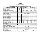
Страница 14: ...n du moteur Amp 4 3 4 3 4 3 9 1 9 1 Consommation des éléments électriques Amp 61 74 82 94 111 Consommation totale Amp 65 3 78 3 86 3 103 1 120 1 Ampérage du circuit dimensionnement du conducteur 2 82 98 108 130 150 Disjoncteur maximum du circuit Amp 2 90 100 110 150 150 Moteur HP Type Dimension du ventilateur Dimension hors tout larg X long X haut Alimentation Retour Quantité et dimension des filt...

Страница 15: ... Position Fil Jaune YEL LO CFM CONTINUOUS FAN Position Fil Jaune YEL MED CFM CONTINUOUS FAN Position Fil Jaune YEL HI 36 3 0 600 960 1200 30 2 5 500 800 1000 24 2 0 400 640 800 18 1 5 300 480 600 VENTILATION CONTINUE Signal 24 VAC R sur G seulement CFM quand AC HP CFM ADJUST est à la position NOM CFM inférieur ou supérieur de 10 si AC HP CFM ADJUST est à la position LO ou HI Ajustement HEAT KW CFM...

Страница 16: ...UOUS FAN Position Fil Jaune YEL LO CFM CONTINUOUS FAN Position Fil Jaune YEL MED CFM CONTINUOUS FAN Position Fil Jaune YEL HI 60 5 0 1000 1600 2000 48 4 0 800 1280 1600 42 3 5 700 1120 1400 36 3 0 600 960 1200 VENTILATION CONTINUE Signal 24 VAC R sur G seulement CFM quand AC HP CFM ADJUST est à la position NOM CFM inférieur ou supérieur de 10 si AC HP CFM ADJUST est à la position LO ou HI Ajusteme...

Страница 17: ...17 COMPOSANTES ET PIÈCES DE REMPLACEMENT ...

Страница 18: ...18 LISTE DE PIÈCES Vue explosée B50081 Rev B ...

Страница 19: ... 17B B03521 02 ASS CARTE ÉLECTRONIQUE MOTEUR 1 0 HP 18 20 23 et 27 KW 18 L01H030 RELAIS DPST 22VDC 19 R99G006 REDRESSEUR 22 VDC 20 R99G007 REDRESSEUR TEMPORISATEUR 22 VDC 5 ET 8 SECONDES 21 B03533 KIT ÉLECTRIQUE POUR RELAIS 22 L99F004 BLOC TERMINAL 3 POLES 23A L01H009 RELAIS SPDT 24 VAC Option pour HUM ou EAC 23B L01H011 RELAIS SPDT 120 VAC Option pour HUM ou EAC 24 B03280 PORTE COMPARTIMENT ÉLECT...

Страница 20: ...er with the unit or its controls Call a qualified service technician Printed in Canada Printed on 100 recycled paper DNS 0981 Rev A MULTI POSITION VARIABLE SPEED BLOWER MOTOR ECM INSTALLER SERVICE TECHNICIAN USE THE INFORMATION IN THIS MANUAL FOR THE INSTALLATION AND SERVICING OF THE FURNACE AND KEEP THE DOCUMENT NEAR THE UNIT FOR FUTURE REFERENCE HOMEOWNER PLEASE KEEP THIS MANUAL NEAR THE FURNACE...

Страница 21: ...ENCE 9 3 4 AIRFLOW VERIFICATION 9 4 MAINTENANCE 10 4 1 AIR FILTER 10 4 2 MOTOR LUBRICATION 10 5 INFORMATION 11 TABLES AND FIGURES FIGURE 1 CONFIGURATION UPFLOW INSTALLATION 4 FIGURE 2 CONFIGURATION DOWNFLOW INSTALLATION 4 FIGURE 3 CONFIGURATION HORIZONTAL INSTALLATION 4 FIGURE 4 FAN CONTROL BOARD 6 FIGURE 5 HUMIDIFIER WIRING HUM1 HUM2 8 FIGURE 6 HUMIDIFIER WIRING C W 8 FIGURE 7 ELECTRONIC AIR FILT...

Страница 22: ...unqualified persons can result in hazards to them and to others Installations must conform to local codes or in the absence of same to codes of the country having jurisdiction The information contained in this manual is intended for use by a qualified technician familiar with safety procedures and who is equipped with the proper tools and test instruments Failure to carefully read and follow all i...

Страница 23: ...luding 20 k W can be installed with a zero clearance to combustible material Ducts for furnaces of 23 kW or more must have a clearance of 25 mm 1 to combustible material for the first 0 9 m 36 of duct Thereafter the clearance can be zero Units of 23 kW and up installed in the downflow position must use a DFB FEM downflow base which is especially designed for this purpose It ensures that the requir...

Страница 24: ...alled to control the temperature of the area to be heated Follow the instructions supplied with the thermostat Install the thermostat on an interior wall in a location where it will not be subject to direct sun light lamps air diffusers fireplaces etc Seal openings in walls to avoid air currents that may influence the operation of the thermostat Also refer to the wiring diagrams provided with the ...

Страница 25: ...ntrol Board taps are used by the installer to configure a system The ECM motor uses the selected taps to modify its operation to a pre programmed table of airflows Refer to Table 3 and Table 4 Airflows are based on system size or mode of operation and those airflows are modified in response to thermostat inputs FEM electric furnace must be configured to operate properly with system components with...

Страница 26: ...a thermostat is utilized to perform delay functions 4 ENH enhanced selection provides a 30 second ON delay with no airflow followed by 150 seconds at 70 airflow and no OFF delay for added comfort This profile will minimize cold blow in heat pump operation and could enhance system efficiency 2 6 6 Continuous fan Select desired fan speed when thermostat is set on continuous fan Refer to figure 4 and...

Страница 27: ...he same time Refer to the instructions provided with the thermostat or the Fossil Fuel kit for the proper wiring of the furnace and the heat pump The simultaneous operation of the electric elements and the heat pump will cause overheating of either unit The safety controls of the appliances will shut down the elements or heat pump since they are not designed to function in this fashion 3 OPERATION...

Страница 28: ...t heating mode 1 stage Thermostat closes circuit R to W1 or W2 Furnace delivers the selected electric heat airflow and maximum heating capacity Is powered within a maximum delay of 8 seconds 3 3 6 Electric heat heating mode 2 stage NOTE Remove jumper J2 on board to activate this function Refer to Figures 4 and 9 First stage heating thermostat closes circuit R to W1 Furnace delivers low stage heati...

Страница 29: ...ll la qualified service technician If the temperature rise exceeds the temperature specified 5 F in Table 2 move the AC HP CFM ADJUST black wire to high HI position If the excessive temperature rise cannot be reduced by increasing fan speed investigate for ductwork obstructions or dirty and improper air filter When calling for service or ordering a replacement part specify the model and serial num...

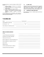
Страница 30: ...me and address START UP RESULTS Voltage Total current consumed by the elements Supply air temperature Return air temperature Supply air duct static pressure Return air duct static pressure Total pressure Calculated air flow Current consumed by the blower motor Current consumed by the accessories 11 ...

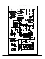
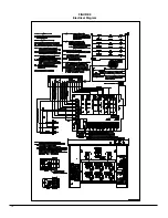
Страница 31: ...12 FIGURE 9 Electrical Diagram ...

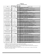
Страница 32: ...lected Cooling CFM OFF Compressor OFF Fan OFF after selected cooling delays ON Compressor ON Fan ON after delays at 80 of the selected Cooling CFM OFF Compressor OFF Fan OFF after selected cooling delays ON Compressor ON Fan ON after delays at 80 of the selected Heat Pump CFM OFF Compressor OFF Fan OFF after selected Heat Pump delays ON Compressor ON Fan ON after delays at selected Heat Pump CFM O...

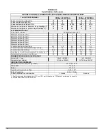
Страница 33: ... Kw 5 5 Electrical element 6 Kw 5 Blower motor Consumption Amp 4 3 4 3 4 3 9 1 9 1 Heating Elements Consumption Amp 61 74 82 94 111 Total Consumption Amp 65 3 78 3 86 3 103 1 120 1 Circuit amperage wire sizing 2 82 98 108 130 150 Maximum size circuit breaker Amp 2 90 100 110 150 150 Motor HP Type Blower size Overall dimensions width x depth x height Supply Return Filter quantity and size Shipping ...

Страница 34: ...ze TONS CFM CONTINUOUS FAN YELLOW wire position LO CFM CONTINUOUS FAN YELLOW wire position MED CFM CONTINUOUS FAN YELLOW wire position HI 36 3 0 600 960 1200 30 2 5 500 800 1000 24 2 0 400 640 800 18 1 5 300 480 600 CONTINUOUS FAN 24 VAC R input on G only CFM s when AC HP CFM ADJUST at NOM position CFM s 10 lower or higher if AC HP CFM ADJUST at LO or HI position HEAT KW CFM adjustment RED wire po...

Страница 35: ...M CONTINUOUS FAN YELLOW wire position LO CFM CONTINUOUS FAN YELLOW wire position MED CFM CONTINUOUS FAN YELLOW wire position HI 60 5 0 1000 1600 2000 48 4 0 800 1280 1600 42 3 5 700 1120 1400 36 3 0 600 960 1200 CONTINUOUS FAN 24 VAC R input on G only CFM s when AC HP CFM ADJUST at NOM position CFM s 10 lower or higher if AC HP CFM ADJUST at LO or HI position HEAT KW CFM adjustment RED wire positi...

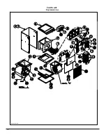
Страница 36: ...17 COMPONENTS AND REPLACEMENT PARTS ...

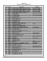
Страница 37: ...18 PARTS LIST Exploded view B50081 Rev B ...

Страница 38: ...A B03521 01 ELECTRONIC BOARD ASSEMBLY 1 2 HP MOTOR 15 18 20 et 23 KW 17B B03521 02 ELECTRONIC BOARD ASSEMBLY 1 HP MOTOR 18 20 23 et 27 KW 18 L01H030 RELAY DPST 22VDC 19 R99G006 RECTIFIER CONTROL 22VDC 20 R99G007 RECTIFIER TIMER CONTROL 5 AND 8 SECONDS 21 B03533 ELECTRICAL KIT FOR RELAYS 22 L99F004 TERMINAL BLOCK 3 POLES 23A L01H009 RELAY SPDT 24 VAC Option for HUM or EAC 23B L01H011 RELAY SPDT 120...

Отзывы: