5
2.4 ELECTRICAL
SYSTEM
The
SUPREME
furnace is completely pre-wired and all field
wiring must be connected to the terminal blocks on the unit. It
requires a 240 volt, 2-wire power supply.
WARNING
Risk of fire.
The conductor sizing must conform to the last edition of
the local or national codes.
Failure to follow this rule can result in death, bodily injury
and/or property damage.
Power supply to the unit can be made using copper or
aluminum wires. The wire size must be decided in accordance
to unit power consumption, the over current protection type and
capacity, the wire type and length, and the environment where
the unit is installed. If an aluminum wire is used, other
precautions must be taken to insure the conformity of the
installation. In all cases, all the factors affecting the wire gauge
must be considered and the installation codes followed.
The exterior of the unit must have an uninterrupted ground to
minimize the risk of bodily harm. A ground terminal is supplied
with the control box for that purpose.
In the event that wires inside the unit require replacement, these
must be copper wires only with same temperature rating as
originals.
2.5
INSTALLATION OF THE THERMOSTAT
A thermostat must be installed to control the temperature of the
area to be heated. Follow the instructions supplied with the
thermostat. Install the thermostat on an interior wall in a
location where it will not be subject to direct sun light, lamps, air
diffusers, fireplaces, etc. Seal openings in walls to avoid air
currents that may influence the operation of the thermostat.
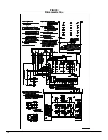
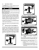
Also refer to the wiring diagrams provided with the heating/air
conditioning unit. The connections must be made as indicated
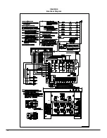
on the following diagrams and the electrical diagram, Figure 9,
p.12.
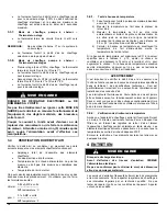
1-stage thermostat, heating only
2-stage thermostat, heating only
2-stage heating & 1-stage air conditioning & heat pump
thermostat
2-stage heating & 2-stage air conditioning & heat pump
ther dehumidification mode
2.5.1.
Thermostat heat anticipator adjustment (if
required)
Certain thermostats are equipped with a heat anticipator that
must be adjusted according to the instructions supplied. This is
to ensure that the heating mode is comfortable and economical.
Generally speaking, on a single stage thermostat, a reading of
the current must be taken with an ammeter as follows:
1) Move the anticipator to its highest setting, rendering it
ineffective.
2) Remove the wire from the “W1” terminal and connect
an ammeter between the terminal and the wire.
3) Call for heat by raising the set point on the thermostat
and allow the furnace to run for 3 to 4 minutes to reach
its peak output.
Содержание FEM15-E230V1M-A
Страница 12: ...12 FIGURE 9 Diagramme électrique ...
Страница 17: ...17 COMPOSANTES ET PIÈCES DE REMPLACEMENT ...
Страница 18: ...18 LISTE DE PIÈCES Vue explosée B50081 Rev B ...
Страница 31: ...12 FIGURE 9 Electrical Diagram ...
Страница 36: ...17 COMPONENTS AND REPLACEMENT PARTS ...
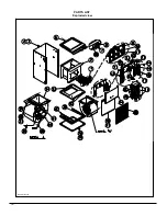
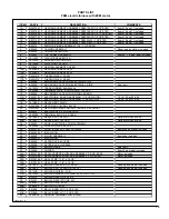
Страница 37: ...18 PARTS LIST Exploded view B50081 Rev B ...

