8
2.7.1.
Humidifier and humidistat connection
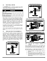
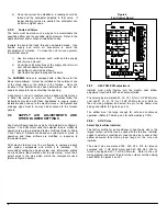
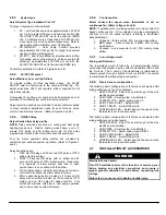
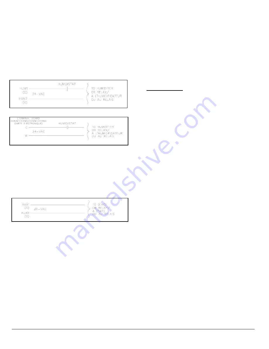
Fan Control Board terminals HUM1 (directly connected
internally to C on terminal block) and HUM2 (directly connected
internally to G on terminal block) are provided for direct
connections to the low-voltage control of a humidifier through a
standard humidistat (refer to Figure 5). These terminals are
energized with 24 VAC when G thermostat signal is present.
Alternately, the 24 VAC signal may be sourced from the W1 and
C terminal block connections when electric heaters are used as
a primary heating source (refer to Figure 6).
Figure 5
Figure 6
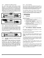
2.7.2.
Electronic Air Cleaner (EAC) connections
Fan Control Board terminals AUX1 (directly connected internally
to C on terminal block) and AUX2 (directly connected internally
to G on terminal block) are provided for direct connections to the
low-voltage control of an electronic air cleaner (EAC). These
terminals are energized with 24 VAC when G thermostat signal
is present (refer to Figure 7).
Figure 7
2.7.3.
Dehumidify capability with standard humidistat
connection
Latent capacities for systems using this unit are better than
average systems. If increased latent capacity is an application
requirement, the field wiring terminal block provides a
connection terminal (DH) for use of a standard humidistat. The
furnace control will detect the humidistat contact opening on
increasing humidity and reduce its airflow to approximately 80%
of nominal cooling mode airflow. This reduction will increase
the system latent capacity until the humidity falls to a level which
causes the humidistat contact to close its contacts.
2.7.4.
Use of a heat pump
When using a heat pump, a thermostat with dial fuel option or a
fossil fuel kit is required that prevents the operation of the
electric elements and the heat pump at the same time. Refer to
the instructions provided with the thermostat or the “Fossil Fuel”
kit for the proper wiring of the furnace and the heat pump.
The simultaneous operation of the electric elements and the
heat pump will cause overheating of either unit. The safety
controls of the appliances will shut down the elements or heat
pump, since they are not designed to function in this fashion.
3 OPERATION
3.1 START-UP
Before starting up the unit, be sure to check that the following
items are in compliance:
1) The electrical installation and ventilation;
2) The blower access door is in place and the blower rail
locking screws are well tightened;
3) The blower speed adjustments for heating and air
conditioning are appropriate and according to the
specifications in this manual;
4) The thermostat of the room is in the heating mode and
is set higher than the ambient temperature.
To start the unit, turn the main electrical switch on.
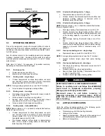
3.2
USE OF MANUAL FURNACE CONTROLS
When there is a demand for heat, the pilot light (“L-1”) comes
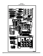
on. Refer to the wiring diagram.
When the ”HI/LO” switch is put into the “LO” position, it will shut
down approximately half the elements.
However, it is important to put the switch back to the “HI”
position during the winter months to ensure adequate
heating.
Also, this switch must remain in the “HI” position when a 2-stage
or outdoor thermostat is used to control the electric elements of
the second stage. Refer to the diagram in Section 1.5) above
(Typical 24 VAC Wiring, Thermostat).
The “ON/OFF VENT/FAN” switch engages the blower in the
continuous speed mode. This will filter the air and provide for
better air distribution in the building.
The circuit breaker is there to protect the motor and control
circuit conductors. If the unit does not function, press the circuit
breaker button to see if it may have disengaged due to a power
surge. If the breaker has to be pressed again, the unit must be
checked by a qualified service technician.
DNS-1154 Rev. A
DNS-1154 Rev. A
DNS-1154 Rev. A
Содержание FEM15-E230V1M-A
Страница 12: ...12 FIGURE 9 Diagramme électrique ...
Страница 17: ...17 COMPOSANTES ET PIÈCES DE REMPLACEMENT ...
Страница 18: ...18 LISTE DE PIÈCES Vue explosée B50081 Rev B ...
Страница 31: ...12 FIGURE 9 Electrical Diagram ...
Страница 36: ...17 COMPONENTS AND REPLACEMENT PARTS ...
Страница 37: ...18 PARTS LIST Exploded view B50081 Rev B ...

