background image

S

UPER

S

ERVER

6017R-TDLF


S

UPER

®

USER’S MANUAL

1.0

Содержание SUPERSERVER 6017R-TDLF

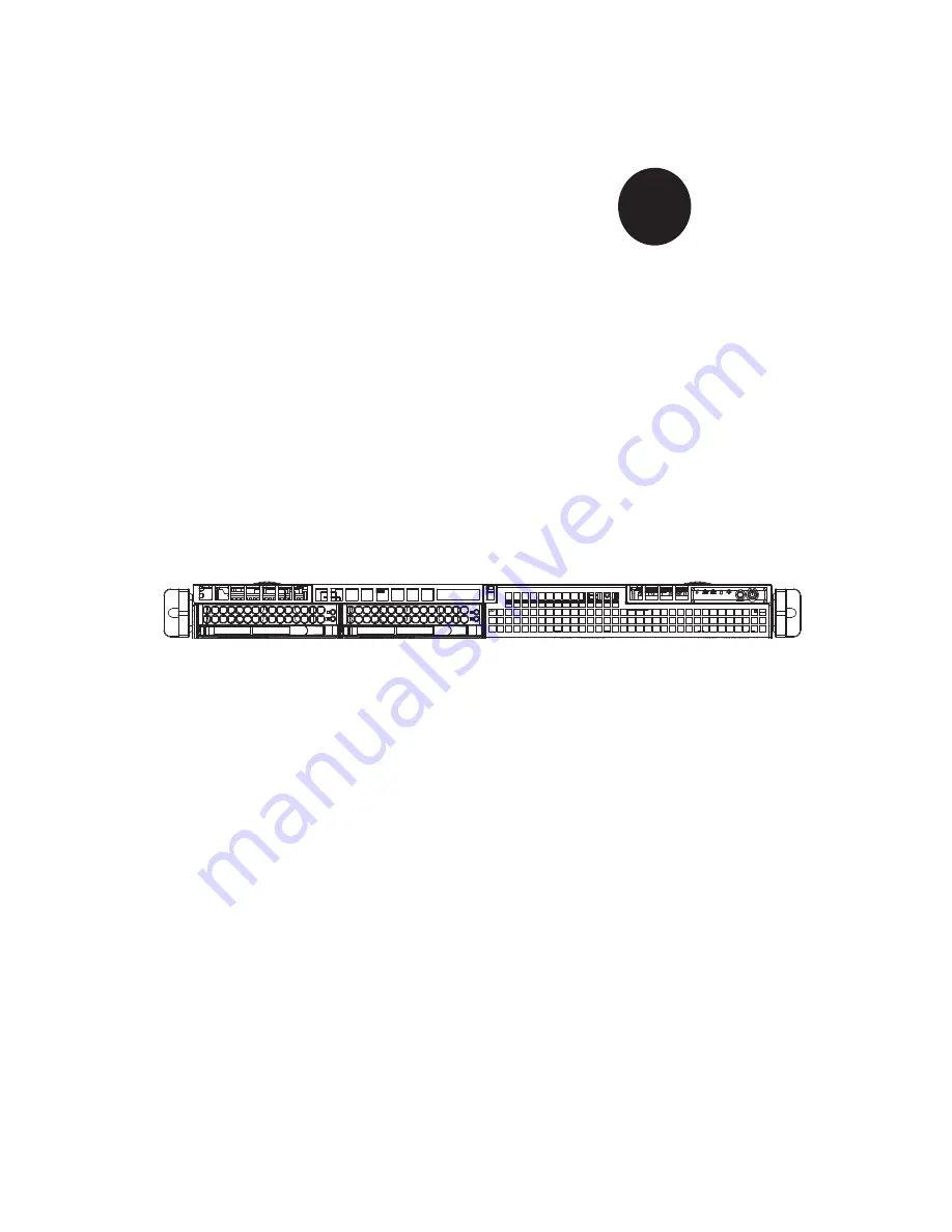
Страница 1: ...SUPERSERVER 6017R TDLF SUPER USER S MANUAL 1 0...

Страница 2: ...any such disputes Super Micro s total liability for all claims will not exceed the price paid for the hardware product FCC Statement This equipment has been tested and found to comply with the limits...

Страница 3: ...813LT 350CB chassis Chapter 2 Server Installation This chapter describes the steps necessary to install the SuperServer 6017R TDLF into a rack and check out the server configuration prior to powering...

Страница 4: ...he serverboard Chapter 6 Advanced Chassis Setup Refer to Chapter 6 for detailed information on the SC813LT 350CB server chassis You should follow the procedures given in this chapter when installing r...

Страница 5: ...v Preface Notes...

Страница 6: ...npacking the System 2 1 2 3 Preparing for Setup 2 1 Choosing a Setup Location 2 2 2 4 Warnings and Precautions 2 2 Rack Precautions 2 2 Server Precautions 2 2 Rack Mounting Considerations 2 3 Ambient...

Страница 7: ...Backplane Voltage 4 13 Comply with Local and National Electrical Codes 4 14 Product Disposal 4 15 Hot Swap Fan Warning 4 16 Power Cable and AC Adapter 4 18 Chapter 5 Advanced Serverboard Setup 5 1 Han...

Страница 8: ...ving the Front Bezel 6 5 Accessing the Drive Bays 6 5 SATA Drive Installation 6 6 SATA Power Cables 6 7 SATA Backplane 6 7 CD ROM Drive Installation 6 8 6 5 Power Supply 6 9 Power Supply Fail 6 9 Chap...

Страница 9: ...ncluded with the 6017R TDLF as listed below Two 10 cm blower fans FAN 0135L4 Two passive CPU heatsinks SNK P0047PS SATA Accessories One SATA backplane BPN SAS 813LT O P Four 3 5 hard drive carriers MC...

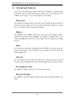
Страница 10: ...8 DIMM sockets that can support up to 256GB of DDR3 1600 1333 1066 800 registered RDIMM Load Reduced LRDIMM ECC or Un buffered UDIMM ECC non ECC memory Please refer to Chapter 5 for installing memory...

Страница 11: ...appable units Control Panel The SC813LT 350CB s control panel provides important system monitoring and control information LEDs indicate power on network activity hard disk drive activ ity and system...

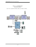
Страница 12: ...A B C D A B C D PE2 PE2 PE3 PE3 CPU0 LEFT PE2 DMI DMI PET 1 4 PEG0 0 3 x4 Lane 1 4 SATA GEN 3 LPC USB USB PET8 P0 P1 B E5 2600 DDR3 DIMM DDR3 DIMM 1 F E 1 DDR3 DIMM DDR3 DIMM 1 G 1 PE2 CPU1 RIGHT P1 P...

Страница 13: ...ress Super Micro Computer B V Het Sterrenbeeld 28 5215 ML s Hertogenbosch The Netherlands Tel 31 0 73 6400390 Fax 31 0 73 6416525 Email sales supermicro nl General Information support supermicro nl Te...

Страница 14: ...1 6 SUPERSERVER 6017R TDLF User s Manual Notes...

Страница 15: ...m with the carrier who delivered it Decide on a suitable location for the rack unit that will hold the SuperServer 6017R TDLF It should be situated in a clean dust free area that is well ventilated Av...

Страница 16: ...installation stabilizers should be attached to the rack In multiple rack installations the racks should be coupled together Always make sure the rack is stable before extending a component from the r...

Страница 17: ...sible overloading of circuits might have on overcurrent protection and power supply wiring Appropriate consideration of equipment nameplate ratings should be used when addressing this concern Reliable...

Страница 18: ...market which may mean the assembly procedure will differ slightly You should also refer to the installation instructions that came with the rack unit you are using Note This rail will fit a rack betw...

Страница 19: ...e secured to the rack 2 Adjust both sections of the outer rail to the proper length so that the rail fits snugly within the rack 3 Secure the longer section of the outer rail to the of the rack with t...

Страница 20: ...2 6 SUPERSERVER 6017R TDLF User s Manual Figure 2 3 Installing the Outer Rails to the Server Rack 1 2 1 3 1 3...

Страница 21: ...s been pushed completely into the rack you should hear the locking tabs click into the locked position 3 Optional Insert and tighten the thumbscrews that hold the front of the server to the rack 1 A 1...

Страница 22: ...etermine how far follow the server will extend out the front of the rack Larger chassis should be positioned to balance the weight between front and back If a bezel is included on your server remove i...

Страница 23: ...ol panel and an on off switch on the power supply This chapter explains the meanings of all LED indicators and the appropriate response you may need to take 3 2 Control Panel Buttons There are two pus...

Страница 24: ...red continuously it indicates an overheat condition which may be caused by cables obstructing the airflow in the system or the ambient room temperature being too warm Check the routing of the cables a...

Страница 25: ...carrier has two LEDs Green When illuminated the green LED on the drive carrier indicates drive activity A connection to the backplane enables this LED to blink on and off when that particular drive is...

Страница 26: ...3 4 SUPERSERVER 6017R TDLF User s Manual Notes...

Страница 27: ...nt for assistance Only certified technicians should attempt to install or configure components Read this appendix in its entirety before installing or configuring components in the Supermicro chassis...

Страница 28: ...considere los riesgos de la corriente el ctrica y familiar cese con los procedimientos est ndar de prevenci n de accidentes Al final de cada advertencia encontrar el n mero que le ayudar a encontrar e...

Страница 29: ...l kan veroorzaken Voordat u aan enige apparatuur gaat werken dient u zich bewust te zijn van de bij een elektrische installatie betrokken risico s en dient u op de hoogte te zijn van de standaard proc...

Страница 30: ...e en des Systems an die Stromquelle die Installationsanweisungen lesen Advertencia Lea las instrucciones de instalaci n antes de conectar el sistema a la red de alimentaci n Attention Avant de branche...

Страница 31: ...ert ist Stellen Sie sicher dass der Nennwert der Schutzvorrichtung nicht mehr als 250 V 20 A betr gt Advertencia Este equipo utiliza el sistema de protecci n contra cortocircuitos o sobrecorrientes de...

Страница 32: ...ift um Systemsbestandteile anzubringen oder zu entfernen Warning The system must be disconnected from all sources of power and the power cord removed from the power supply module s before accessing th...

Страница 33: ...nentes de sistema Attention Le syst me doit tre d branch de toutes les sources de puissance ainsi que de son cordon d alimentation secteur avant d acc der l int rieur du chassis pour installer ou enle...

Страница 34: ...rnung Das Installieren Ersetzen oder Bedienen dieser Ausr stung sollte nur geschultem qualifiziertem Personal gestattet werden Advertencia Solamente el personal calificado debe instalar reemplazar o u...

Страница 35: ...stallation in Bereichen mit beschr nktem Zutritt vorgesehen Der Zutritt zu derartigen Bereichen ist nur mit einem Spezialwerkzeug Schloss und Schl ssel oder einer sonstigen Sicherheitsvorkehrung m gli...

Страница 36: ...me or equivalent type recommended by the manufacturer Dispose of used batteries according to the manufacturer s instructions Waarschuwing Dit apparaat is bedoeld voor installatie in gebieden met een b...

Страница 37: ...ecommand e par le fabricant Jeter les piles usag es conform ment aux instructions du fabricant Advertencia Existe peligro de explosi n si la bater a se reemplaza de manera incorrecta Reemplazar la bat...

Страница 38: ...para fuentes de alimentaci n Para cortar por completo el suministro de energ a deben desconectarse todas las conexiones Attention Cette unit peut avoir plus d une connexion d alimentation Pour supprim...

Страница 39: ...ero es peligroso Tenga cuidado cuando lo revise Attention Lorsque le syst me est en fonctionnement des tensions lectriques circulent sur le fond de panier Prendre des pr cautions lors de la maintenanc...

Страница 40: ...ectrical codes Warnung Die Installation der Ger te muss den Sicherheitsstandards entsprechen Advertencia La instalacion del equipo debe cumplir con las normas de electricidad locales y nacionales Back...

Страница 41: ...ional laws and regulations Attention L quipement doit tre install conform ment aux normes lectriques nationales et locales Waarschuwing Bij installatie van de apparatuur moet worden voldaan aan de lok...

Страница 42: ...seguir todas las leyes y reglamentos nacionales Attention La mise au rebut ou le recyclage de ce produit sont g n ralement soumis des lois et ou directives de respect de l environnement Renseignez vou...

Страница 43: ...dedos los destornilladores y todos los objetos lejos de las aberturas del ventilador Attention Il est possible que les ventilateurs soient toujours en rotation lorsque vous retirerez le bloc ventilat...

Страница 44: ...dapter kann zu einer Fehlfunktion oder ein Brand entstehen Elektrische Ger te und Material Safety Law verbietet die Verwendung von UL oder CSA zertifizierte Kabel UL oder CSA auf der Code f r alle and...

Страница 45: ...utres appareils lectriques que les produits d sign s par Supermicro seulement AC AC UL CSA UL CSA UL CSA Supermicro UL CSA AC Electrical Appliance and Material Safety Law UL CSA UL CSA Waarschuwing Bi...

Страница 46: ...4 20 SUPERSERVER 6017R TDLF User s Manual Notes...

Страница 47: ...hat the size and weight of the serverboard can cause it to bend if handled improperly which may result in damage To prevent the serverboard from bending keep one hand under the center of the board to...

Страница 48: ...you install the CPU heatsinks When receiving a serverboard without a processor pre installed make sure that the plastic CPU socket cap is in place and none of the socket pins are bent otherwise conta...

Страница 49: ...ARNING plastic cap from the socket 5 Use your thumb and index finger to hold the CPU by its edges Align the CPU keys which are semi circle cutouts against the socket keys 6 Once they are aligned caref...

Страница 50: ...gain and double check that the CPU is aligned properly 7 With the CPU in the socket in spect the four corners of the CPU to make sure that they are flush with the socket 8 Close the load plate Lock th...

Страница 51: ...ghten all four screws Removing the Heatsink Warning We do not recommend removing the CPU or the heatsink However if you do need to remove the heatsink please follow the instructions below to prevent d...

Страница 52: ...he cables The following data cables with their serverboard connector locations noted should be connected See the serverboard layout diagram in this chapter for connector locations Control Panel cable...

Страница 53: ...s of JF1 5 4 I O Ports The I O ports are color coded in conformance with the PC 99 specification See Figure 5 3 below for the colors and locations of the various I O ports Figure 5 3 Rear Panel I O Po...

Страница 54: ...p 1 to install to DIMM1B if needed Memory Support The X9DRD LF Motherboard Supports up to 256 GB of Registered Unbuffered ECC or LRDIMM DDR3 1600 1333 1066 800 MHz memory in four channel memory via a...

Страница 55: ...DIMMA1 P2 DIMME1 2 CPUs 4 DIMMs CPU1 CPU2 P1 DIMMA1 P1 DIMMB1 P2 DIMME1 P2 DIMMF1 2 CPUs 6 DIMMs CPU1 CPU2 P1 DIMMA1 P1 DIMMB1 P1 DIMMC1 P2 DIMME1 P2 DIMMF1 P2 DIMMG1 2 CPUs 8 DIMMs CPU1 CPU2 P1 DIMMA...

Страница 56: ...LED Blue On Unit Identified LEDM1 BMC Heartbeat LED Green Blinking BMC Normal F1 BMC CTRL LAN CTRL BIOS FP CTRL A1 COM1 1 10 Rev X9DRD LF JBT1 LED2 LEDM1 LED3 JD1 JUIDB JPW4 SP1 JPW3 JPW2 JPW1 JI2C2...

Страница 57: ...N1 4 CPU System Fan Headers JBAT1 Onboard Battery JD1 Speaker Power LED Indicator JF1 Front Panel Control Header JPI2 C1 Power Supply SMBbus I2 C Header JPW1 24 Pin ATX Main Power Connector JPW2 3 12V...

Страница 58: ...9 5VSB 22 5V 10 12V 23 5V 11 12V 24 COM 12 3 3V 12V 8 pin PWR Connector Pin Definitions Pins Definition 1 4 Ground 5 8 12V Required 4 pin PWR Con nector Pin Definitions Pins Definition 1 2 Ground 3 4...

Страница 59: ...lure The Blue LED on pin 8 works as the front panel UID LED indicator The Red LED takes precedence over the Blue LED by default Refer to the table on the right for pin definitions OH Fan Fail PWR Fail...

Страница 60: ...right for pin definitions Power Button Pin Definitions JF1 Pin Definition 1 Signal 2 Ground Serial Port One COM port COM1 is located on the Backplane I O panel on the mother board See the table on the...

Страница 61: ...ch and two LED Indicators are located on the moth erboard The UID Switch is located next to the VGA port on the backplane The Rear UID LED LED3 is located next to the UID Switch The Front Panel UID LE...

Страница 62: ...an be used to provide audible indications for various beep codes See the table on the right for pin definitions Internal Buzzer SP1 Pin Definition Pin Definitions Pin 1 Pos Beep In Pin 2 Neg Alarm Spe...

Страница 63: ...anel to use the Overheat Fan Fail Power Fail and UID LED connections The Red LED on pin 7 provides warnings of overheat fan failure or power failure The Blue LED on pin 8 works as the front panel UID...

Страница 64: ...Explanation of Jumpers To modify the operation of the mother board jumpers can be used to choose between optional settings Jumpers cre ate shorts between two pins to change the function of the connec...

Страница 65: ...s Jumper Settings Jumper Setting Definition Closed Enabled Default Open Disabled BMC Enable Jumper JPB1 allows you to enable the embedded WPCM 450 BMC Baseboard Management Controller to provide IPMI 2...

Страница 66: ...amber LED on the right indicates activity while the green LED on the left indicates the speed of the connection See the tables at right for more information Link LED Activity LED IPMI LAN IPMI LAN Li...

Страница 67: ...ns Pin Definition 1 Ground 2 TX_P 3 TX_N 4 Ground 5 RX_N 6 RX_P 7 Ground SATA Connectors There are two SATA 3 0 ports on the motherboard I SATA 0 1 provide serial link signal connections which are fas...

Страница 68: ...Website at http www supermicro com products Find the product page for your motherboard here where you may down load individual drivers and utilities After creating a CD DVD with the ISO files insert t...

Страница 69: ...mperature system voltages and fan status See the figures below for examples of the SuperDoctor III interface Note The default User Name and Password for SuperDoctor III is ADMIN ADMIN Note When SuperD...

Страница 70: ...User s Manual can be downloaded from the Supermicro web site at http www supermicro com products accessories soft ware SuperDoctorIII cfm For Linux we recommend that you use the SuperDoctor II applica...

Страница 71: ...ice is not strictly followed Figure 5 9 Installing the Onboard Battery LITHIUM BATTERY BATTERY HOLDER Please handle used batteries carefully Do not damage the battery in any way a damaged battery may...

Страница 72: ...5 26 SUPERSERVER 6017R TDLF User s Manual Notes...

Страница 73: ...mage to any printed circuit boards PCBs it is important to handle them very carefully The following measures are generally sufficient to protect your equipment from ESD damage Precautions Use a ground...

Страница 74: ...e header on the Control Panel PCB printed circuit board Make sure the red wire plugs into pin 1 on both connectors Pull all excess cabling out of the airflow path The control panel LEDs inform you of...

Страница 75: ...either side and pull the unit straight out until it locks you will hear a click 2 Depress the two buttons on the top of the chassis to release the top cover Push the cover away from you until it stops...

Страница 76: ...6 4 SUPERSERVER 6017R TDLF Manual Figure 6 3 Removing System Cooling Fans Figure 6 2 Accessing the Inside of the System Release buttons...

Страница 77: ...t since its condition will affect the airflow throughout the whole system Accessing the Drive Bays Serial ATA Drives Because of their hotswap capability you do not need to access the inside of the cha...

Страница 78: ...w for the Serial ATA drive bays For this reason even empty carriers without drives installed must remain in the chassis 1 Remove the two screws securing the dummy drive to the drive tray 2 Lift the du...

Страница 79: ...ray us ing the drive tray handle SATA Power Cables Serial ATA power cables should be routed so that they do not block the airflow through the chassis See the serverboard layout diagram for the locatio...

Страница 80: ...sis cover removed unplug the power and data cables from the drive you want to remove 2 Locate the locking tab at the rear of the drive It will be on the left side of the drive when viewed from the fro...

Страница 81: ...Unplug the power cord from the system 2 To remove the failed power unit remove the two screws on the back of the power supply which secure it to the chassis You can then lift the unit straight out of...

Страница 82: ...6 10 SUPERSERVER 6017R TDLF Manual Figure 6 7 Removing Replacing the Power Supply...

Страница 83: ...e user The right frame displays the key legend Above the key legend is an area reserved for a text message When an option is selected in the left frame it is highlighted in white Often a text message...

Страница 84: ...orner of the screen below the copyright message Warning Do not upgrade the BIOS unless your system has a BIOS related issue Flashing the wrong BIOS can cause irreparable damage to the system In no eve...

Страница 85: ...2011 System Time This item displays the system time in HH MM SS format e g 15 32 52 Supermicro X9DRD LF Version This item displays the SMC version of the BIOS ROM used in this system Build Date This...

Страница 86: ...ad of the normal POST messages The op tions are Enabled and Disabled AddOn ROM Display Mode Use this item to set the display mode for the Option ROM Select Keep Current to use the current AddOn ROM Di...

Страница 87: ...f the system will power off immediately as soon as the user presses the power button If this feature is set to 4 Seconds Override the system will power off when the user presses the power button for 4...

Страница 88: ...2 supports 64 bit technology Clock Spread Spectrum Select Enable to enable Clock Spectrum support which will allow the BIOS to moni tor and attempt to reduce the level of Electromagnetic Interference...

Страница 89: ...Instruc tions NI to ensure data security The options are Enabled and Disabled Hardware Prefetcher Available when supported by the CPU If set to Enabled the hardware prefetcher will prefetch streams of...

Страница 90: ...Efficiency and Custom If the option is set to Custom the following items will display EIST Available when Power Technology is set to Custom EIST Enhanced Intel SpeedStep Technology allows the system...

Страница 91: ...ce This setting allows the user to adjust the fan speed based on performance maxi mum cooling or energy efficiency maximum energy savings The options are Performance Balanced Performance Balanced Ener...

Страница 92: ...ability security and availability in networking and data sharing The options are Enabled and Disabled Intel I OAT The Intel I OAT I O Acceleration Technology significantly reduces CPU over head by lev...

Страница 93: ...n This section displays the following DIMM information Current Memory Mode This item displays the current memory mode Current Memory Speed This item displays the current memory speed Mirroring This it...

Страница 94: ...ors detected on a memory module and send the correction to the requestor the original source When this item is set to Enabled the IO hub will read and write back one cache line every 16K cycles if the...

Страница 95: ...troller 2 Available when All USB Devices is set to Enabled Select Enabled to enable EHCI Enhanced Host Controller Interface Controller 1 or Controller 2 The options are Disabled and Enabled Legacy USB...

Страница 96: ...d set the compatibility mode The options for Controller 0 are Enhanced and Compat ible The default for SATA Controller 0 is Compatible The default of SATA Controller 1 is Enhanced AHCI Mode The follow...

Страница 97: ...to 64 PCI clock cycles The options are 32 64 96 128 160 192 224 and 248 Above 4G Decoding Available if the system supports 64 bit PCI decoding Select Enabled to decode a PCI device that supports 64 b...

Страница 98: ...oot the computer using a net work interface from the slot specified above The options are Enabled and Disabled Onboard LAN Option ROM Select Select iSCSI to use the iSCSI Option ROM to boot the comput...

Страница 99: ...specified The default setting is Auto which will allow the AMI BIOS to automatically select the best setting for the PECI platform Device Mode Use this feature to select the desired mode for a serial...

Страница 100: ...e to set the data transmission size for Console Redirection The options are 7 Bits and 8 Bits Parity A parity bit can be sent along with regular data bits to detect data transmission errors Select Eve...

Страница 101: ...x XTERMR6 SC0 ESCN and VT400 Serial Port for Out of Band Management Windows Emergency Management Services EMS The submenu allows the user to configure Console Redirection settings to sup port Out of B...

Страница 102: ...iguration TPM Support Select Enabled on this item and enable the TPM jumper on the motherboard to enable TPM support to improve data integrity and network security The options are Enabled and Disabled...

Страница 103: ...at need to be enabled for the Intel Trusted Execution Technology to work properly in the system VT d Support Intel Virtualization Technology with Direct I O support VT Support Intel Virtualization Tec...

Страница 104: ...bps Half 10Mbps Full 100Mbps Half and 100Mbps full Blink LEDs This feature allows the user to specify the duration for LEDs to blink The range is from 0 15 seconds PORT CONFIGURATION INFORMATION This...

Страница 105: ...gement BIOS Event Logging during system boot The options are Enabled and Disabled Runtime Error Logging Support Select Enabled to support Runtime Error Logging The options are Enabled and Disabled Mem...

Страница 106: ...are Do Nothing and Erase Immediately SMBIOS Event Log Standard Settings Log System Boot Event Select Enabled to log system boot events The options are Disabled and Enabled MECI Multiple Event Count In...

Страница 107: ...t to erase all system event logs upon next system reboot Select Yes On every reset to erase all system event logs upon each system reboot Select No to keep all system event logs after each system rebo...

Страница 108: ...r If Static is selected you will need to know the IP address of this computer and enter it to the system manually in the field If DHCP is selected the BIOS will search for a DHCP Dynamic Host Configur...

Страница 109: ...vides compatibility support for traditional legacy BIOS for system boot The op tions are Enabled Disabled and Auto Boot Option 1 Boot Option 2 Boot Option 3 Use this feature to specify the sequence of...

Страница 110: ...feature to set the Administrator Password which is required to enter the BIOS setup utility The length of the password should be from 3 characters to 8 characters long User Password Use this feature...

Страница 111: ...Reset When you have completed the system configuration changes select this option to save the changes and reboot the computer so that the new system configuration settings can take effect Select Save...

Страница 112: ...User Defaults Select this feature and press Enter to save the current settings as the user s defaults When the dialog box appears asking you if you want to save values as user s defaults click Yes to...

Страница 113: ...system manufacturer for possible repairs These fatal errors are usually communicated through a series of audible beeps The numbers on the fatal error list correspond to the number of beeps for the cor...

Страница 114: ...A 2 SUPERSERVER 6017R TDLF User s Manual Notes...

Страница 115: ...tered RDIMM Load Reduced LRDIMM ECC or Unbuffered UDIMM ECC non ECC memory See the memory section in Chapter 5 for details SATA Controller Intel on chip controller for two SATA ports RAID 0 and 1 supp...

Страница 116: ...n condensing Non Operating Relative Humidity 5 to 95 non condensing Regulatory Compliance Electromagnetic Emissions FCC Class A EN 55022 Class A EN 61000 3 2 3 3 CISPR 22 Class A Electromagnetic Immun...

Страница 117: ...o perform be reasonably expected to result in significant injury or loss of life or catastrophic property damage Accordingly Supermicro dis claims any and all liability and should buyer use or sell su...

Страница 118: ...B 4 SUPERSERVER 6017R TDLF User s Manual Notes...

Отзывы: