49
48
Chapter 4: Motherboard Connections
SuperServer 5019S-MN4 User's Manual
4.3 Ports
Serial Ports
Two COM ports (COM1 & COM2) are located on the motherboard. COM1 is a port located
on the I/O back panel. COM2 is a header located next to COM1.
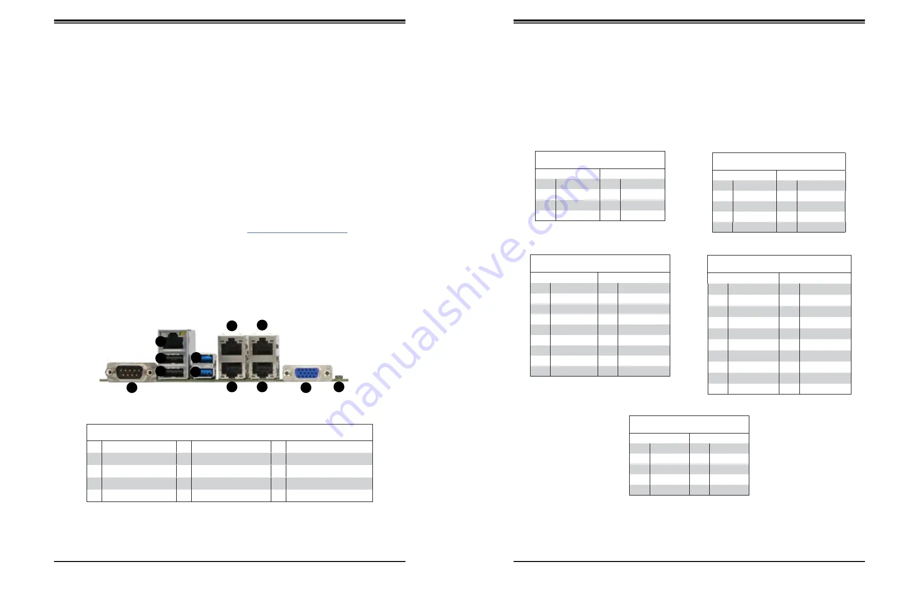
Rear I/O Ports
See the figure below for the locations and descriptions of the various I/O ports on the rear
of the motherboard.
SATA Ports
The X11SSH-LN4F includes a total of eight SATA ports, supported by the Intel C236 PCH
chip. These SATA ports support RAID 0, 1, 5, and 10.
Notes
: I-SATA0 and I-SATA1 are Supermicro SuperDOMs. These are yellow SATADOM ports
with power pins built in and do not require separate external power cables. These ports are
backward-compatible with non-Supermicro SATADOMs that do require external power.
For more information on the SATA HostRAID configuration, please refer to the Intel SATA
HostRAID user's guide posted on our website at
Figure 4-2. Rear I/O Ports
Rear I/O Ports
#
Description
#
Description
#
Description
1.
COM1 Port
5
USB7 (3.0)
9
LAN3 Port
2.
IPMI LAN Port
6
USB6 (3.0)
10 LAN4 Port
3
USB1 (2.0)
7
LAN1 Port
11 VGA Port
4
USB0 (2.0)
8
LAN2 Port
12 UID Switch
1
9
8
7
6
5
4
3
2
10
12
11
Back Panel USB 0/1 (2.0)
Pin Definitions
Pin#
Definition
Pin#
Definition
1
+5V
5
+5V
2
USB_N
6
USB_N
3
USB_P
7
USB_P
4
Ground
8
Ground
Universal Serial Bus (USB) Ports
There are two USB 2.0 ports (USB 0/1) and two USB 3.0 ports (USB 6/7) located on the
rear I/O panel. The X11SSH-LN4F also has two front access USB 2.0 headers (USB2/3 and
USB4/5) and one front access USB 3.0 header (USB8/9). USB10 is a Type A 3.0 header. The
onboard headers can be used to provide front side USB access with a cable (not included).
Front Panel USB 2/3, 4/5 (2.0)
Pin Definitions
Pin#
Definition
Pin#
Definition
1
+5V
2
+5V
3
USB_N
4
USB_N
5
USB_P
6
USB_P
7
Ground
8
Ground
9
Key
10
NC
Back Panel USB 8/9 (3.0)
Pin Definitions
Pin#
Definition
Pin#
Definition
1
VBUS
19
Power
2
Stda_SSRX-
18
USB3_RN
3
St
17
USB3_RP
4
GND
16
GND
5
Stda_SSTX-
15
USB3_TN
6
St
14
USB3_TP
7
GND
13
GND
8
D-
12
USB_N
9
D+
11
USB_P
10
Front Panel USB 6/7 (3.0)
Pin Definitions
Pin#
Definition
Pin#
Definition
A1
VBUS
B1
Power
A2
D-
B2
USB_N
A3
D+
B3
USB_P
A4
GND
B4
GND
A5
Stda_SSRX-
B5
USB3_RN
A6
St
B6
USB3_RP
A7
GND
B7
GND
A8
Stda_SSTX-
B8
USB3_TN
A9
St
B9
USB3_TP
Type A USB 10 (3.0)
Pin Definitions
Pin#
Definition
Pin#
Definition
1
VBUS
5
SSRX-
2
USB_N
6
SSRX+
3
USB_P
7
GND
4
Ground
8
SSTX-
9
SSTX+


