background image

SBI-7125B-T1 Blade Module Main Manual

Содержание SuperBlade Series

Страница 1: ...SuperBlade User s Manual Revison 1 0c...

Страница 2: ...Micro s total liability for all claims will not exceed the price paid for the hardware product FCC Statement This equipment has been tested and found to comply with the limits for a Class A digital de...

Страница 3: ...ded for your use Chapter 2 System Safety You should familiarize yourself with this chapter for a general overview of safety precautions that should be followed when installing and servicing the SuperB...

Страница 4: ...SuperBlade User s Manual iv Notes...

Страница 5: ...Power Cord 1 6 Power Supply Failure 1 6 1 7 Special Design Features 1 7 Operating System Support 1 7 Remote Management 1 7 Computing Density Power 1 7 High Efficiency Power Supplies 1 7 1 8 Contacting...

Страница 6: ...Module Installation 4 4 Configuring the CMM 4 4 CMM Functions 4 7 Local KVM 4 8 Remote KVM over IP 4 8 Remote Storage Virtual Media 4 8 Serial Over LAN SOL 4 8 Monitoring Functions 4 8 Power Consumpt...

Страница 7: ...s A 1 A 2 Environmental Specifications A 2 A 3 Address Defaults A 2 A 4 Power Supply Power Calculations A 3 Appendix B LED Descriptions B 1 B 1 Blade Enclosure LED Descriptions B 1 B 2 Blade Module LE...

Страница 8: ...SuperBlade User s Manual viii Notes...

Страница 9: ...Manually Configure the IP Address 4 6 Figure 4 5 Changing Settings 4 7 Figure 4 6 USB Switch on Rear of CMM 4 9 Figure 4 7 Home Page 4 12 Figure 4 8 Horizontal Spacers for Single Bays 4 14 Figure 4 9...

Страница 10: ...SuperBlade User s Manual x Notes...

Страница 11: ...ponents 5 5 Table A 1 Enclosure Specification Features A 1 Table A 2 Environmental Specification Features A 2 Table A 3 Address Default Features A 2 Table A 4 Power Supply Power Calculations PWS 2K01...

Страница 12: ...SuperBlade User s Manual xii Notes...

Страница 13: ...n operating systems that have been certified for use with the SuperBlade www supermicro com products superblade 1 2 Quickstart Setup This section covers how to quickly get your new SuperBlade system u...

Страница 14: ...ard disk drives into each module See the the user s manual for your purchased blade module from your system s CD ROM for details e Install your blade modules into your SuperBlade chassis See the the u...

Страница 15: ...e Enclosure x1 SBE 710E 10 blade or SBE 714D E 14 blade series Blade Unit minimum of 2 10 or 14 maximum See the the Supermicro website http www supermicro com products superblade for a complete list o...

Страница 16: ...o replace a failed power module while the backup module takes over to keep the system running You must have either two or four power supply modules installed in the blade enclosure four is recommended...

Страница 17: ...modules have two fans per module If a power supply fails its fans will continue to operate to provide continuous cooling For this reason a failed power supply should remain installed in the enclosure...

Страница 18: ...0W power supply module has a C 20 type socket IEC 60320 C20 for AC power and the power cord must have a C 19 type connector IEC 60320 C19 to connect to the power supply Each 1400W power supply module...

Страница 19: ...f your application needs to manage individual blade units at the same time just add a SIMBL add on card to each Blade module Computing Density Power Each SuperBlade mainboard supports two or four proc...

Страница 20: ...uper Micro Computer B V Het Sterrenbeeld 28 5215 ML s Hertogenbosch The Netherlands Tel 31 0 73 6400390 Fax 31 0 73 6416525 Email sales supermicro nl General Information support supermicro nl Technica...

Страница 21: ...ly displayed on the outside of the shipping carton and mailed prepaid or hand carried Shipping and handling charges will be applied for all orders that must be mailed when service is complete This war...

Страница 22: ...SuperBlade User s Manual 1 10 Notes...

Страница 23: ...when using metal tools which can easily damage any electrical components or circuit boards they come into contact with Do not use mats designed to decrease electrostatic discharge as protection from e...

Страница 24: ...and printed circuit boards The following measures are generally sufficient to neutralize this difference before contact is made to protect your equipment from ESD Use a grounded wrist strap designed...

Страница 25: ...section The box the SuperBlade was shipped in should include two sets of rail assemblies two handles and the mounting screws you will need to install the system into the rack Follow the steps in the o...

Страница 26: ...supply UPS to protect the server from power surges voltage spikes and to keep your system operating in case of a power failure Allow the hot plug hard drives and power supply units to cool before tou...

Страница 27: ...STD 607 A 2002 Commercial Building Grounding Earthing and Bonding Requirements for Telecommunications IEEE Std 1100 2005 IEEE Emerald Book IEEE Recommended Practice for Powering and Grounding Electron...

Страница 28: ...pping Release these screws just enough to allow the rails to slide apart Note the arrow on the rail which indicates the end that attaches to the front of the rack 4 Slide the rails apart far enough to...

Страница 29: ...OTE These handles are optional and need only be installed when mounting the system into a short rack When mounting into a deep rack they are unnecessary and regular screws should be used instead of th...

Страница 30: ...SuperBlade User s Manual 3 6 Figure 3 4 Enclosure Installed into Rack...

Страница 31: ...re 4 1 shows a typical module configuration in a blade system See Chapter 5 for information on power supply modules Figure 4 1 Typical Blade System Module Configuration Rear View WARNING All module ba...

Страница 32: ...ideo mouse connection over an out of band TCP IP Ethernet network during any server state functioning blue screen powered down BIOS and so on It also supports Virtual Media VM redirection for CD flopp...

Страница 33: ...in the upper bay will be the master however 2 If the master CMM is powered down or removed the second slave CMM module will then immediately be assigned as the master 6 USB Ports 7 Reset Button 8 Modu...

Страница 34: ...ition 2 Pull the module out of the bay 3 Replace immediately with another module or with a dummy module cover to maintain airflow integrity Configuring the CMM To access configure the CMM you first ha...

Страница 35: ...4 5 Chapter 4 System Modules 3 Choose Internet Protocol TCP IP under the GENERAL tab and click on PROPERTIES seeFigure 4 3 Figure 4 3 Choose Internal Protocol...

Страница 36: ...4 4 Example IP address 192 168 100 101 Subnet Mask 255 255 255 0 Default Gateway 192 168 100 1 5 Once the IP address for the computer system is configured the CMM can be accessed through the web brow...

Страница 37: ...ll scripted commands When the web based browser is used the CMM acts as a web server requiring a higher bandwidth connection to the CMM If there are any bandwidth constraints IPMI will provide a super...

Страница 38: ...n refer to Web based Management Utility on page 4 10 to login and use either utility Remote Storage Virtual Media The Remote Storage function allows the user to connect to a remote storage device such...

Страница 39: ...ot powered on and the front panel LED on the enclosure will blink After the blade is powered on the CMM then collects the actual power consumption of this individual blade and updates the calculated R...

Страница 40: ...ment may be performed with either of three software packages IPMIview IPMItool or a Web based Management utility Any of these utilities are designed to provide an administrator with a comprehensive se...

Страница 41: ...plorer 7 Firefox 2 0 0 7 Netscape 9 03b Network Connection Login To log into the Web based Management Utility 1 Launch a web browser 2 In the address field of the browser enter the IP address that you...

Страница 42: ...the KVM button or via management software 3 Remote Console Screen The active screen from the remote console is displayed here Clicking on this window also accesses the remote console 4 Logout Click on...

Страница 43: ...the two horizontal spacers as shown in Figure 4 8 See Figure 4 9 Step 2 for details 5 Using four screws install the long horizontal spacer to the same space where the two short spacers were removed S...

Страница 44: ...SuperBlade User s Manual 4 14 Figure 4 8 Horizontal Spacers for Single Bays MCP 560 00012 1N for top bay MCP 560 00009 1N for bottom bay...

Страница 45: ...Chapter 4 System Modules Figure 4 9 Modifying for a Double Wide Module Bay Steps 1 2 Step 2 Step 1 Center Support Screws 2 Center Support Horizontal Spacer Screws 4 Horizontal Spacers 2 MCP 560 00012...

Страница 46: ...SuperBlade User s Manual 4 16 Figure 4 10 Modifying for a Double Wide Module Bay Steps 3 4 Step 3 Step 4 Horizontal Spacer Screws 4 Horizontal Spacers 1 Double Wide InfiniBand Module...

Страница 47: ...ure has two models of power supply modules available the PWS 1K41 BR 1400W module Figure 5 1 and the PWS 2K01 BR 2000W module Figure 5 2 The features of these power supplies are shown in Table 5 1 and...

Страница 48: ...ions Temp 5 to 50 C Humidity 5 to 95 RH Fan Type 2x 90mm fans PFC0912DE 6L38 8000 RPM with PWM Table 5 2 PWS 2K01 BR Power Supply Features Feature Description Output 2000W Type Redundant Module N 1 12...

Страница 49: ...udes a management module that monitors the power supplies and the power enclosure Power Supply Failure If a power supply or a fan in a power supply fails the system management software will notify you...

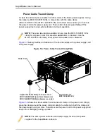
Страница 50: ...Module 3 Pull out the handle and remove the unit the two piece handle locks into the closed position To release the handle squeeze together the two metal plates of the handle with your thumb and finge...

Страница 51: ...t IEC 60320 C14 for AC power and the power cord must have a C 13 type connector IEC 60320 C13 to connect to the power supply See Figure 5 4 for an example of a power cord The plastic locking clip that...

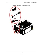
Страница 52: ...rts Figure 5 6 shows how to assemble the cable tie and clamp on the power cord Simply place the clamp around the power cord and attach the cable tie to both the clamp and the power supply using a scre...

Страница 53: ...5 7 Chapter 5 Power Supply Modules Figure 5 6 Power Cable Tie and Clamp Assembly...

Страница 54: ...SuperBlade User s Manual 5 8 Notes...

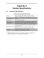
Страница 55: ...r 2000W or 1600W power supplies The SBE 714D E enclosure can only use 1400W power supplies Rated Output Power 2000W Part PWS 2K01 BR C 20 type socket or 1400W Part PWS 1K41 BR C 14 type socket power s...

Страница 56: ...000 4 3 EN 61000 4 4 EN 61000 4 5 EN 61000 4 6 EN 61000 4 8 EN 61000 4 11 Safety EN 60950 IEC 60950 Compliant UL Listed USA CUL Listed Canada TUV Certified Germany CE Marking Europe California Best Ma...

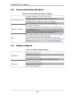
Страница 57: ...gh 90 Efficiency Low 80 Power Factor High 98 Power Factor Low 90 10 Reserve High 1 2 10 Reserve Low 1 0 Amps Total 13 6 240 volts Table A 5 Power Supply Power Calculations PWS 1K41 BR Calculation Valu...

Страница 58: ...SuperBlade User s Manual A 4 Notes...

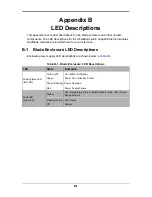
Страница 59: ...B 1 Blade Enclosure LED Descriptions Enclosure power supply LED descriptions are shown below in Table B 1 Table B 1 Blade Enclosure LED Descriptions LED State Indication Power Status LED left LED Yell...

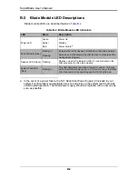
Страница 60: ...rrupted operation The failed power supply should be replaced with a new one as soon as possible KVM UID LED Blue Steady On Indicates that KVM has been initialized on this blade module Flashing Serves...

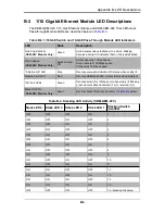
Страница 61: ...bps speed Initiation OK LED Blue Denotes successful initiation OK status when solidly lit Module Fault LED Red Denotes SBM GEM X2C module failure when solidly lit 10G Port LEDs Green Denotes activity...

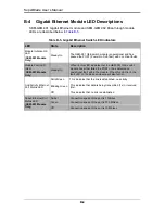
Страница 62: ...ly Steady On When lit this LED indicates that the GEM 001 GbE switch module has either failed the POST or has detected an operational fault within the module When this LED is lit the fault LED on the...

Страница 63: ...properly booted and operational Module Power LED Green Steady On Switch has power and is operational Off There is a problem with the power being supplied to the switch Port Physical Link LED Green Ste...

Страница 64: ...SuperBlade User s Manual B 6 Notes...

Страница 65: ...ted to result in significant injury or loss of life or catastrophic property damage Accordingly Supermicro disclaims any and all liability and should buyer use or sell such products for use in such ul...

Страница 66: ...SBI 7125B T1 Blade Module Main Manual...

Отзывы: