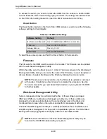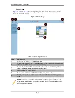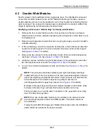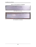
5-3
Chapter 5: Power Supply Modules
Four modules are required when the full complement of 10 blade units are installed into
an enclosure. An LED on the back of a power supply will be amber when AC power is
present and green when the power is on.
When installing only two power supplies in the enclosure, they should be installed in the
lower rather than the upper power bays. This is to provide increased airflow across the
memory modules within each blade module.
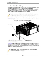
The 2000W power supply modules require a 200-240V AC input and a C20 socket,
which requires a power cord with a C19 connector (see
"Power Cord"
below for details).
The 1400W power supply modules can work with both 110V and 220V AC input and use
a C14 socket and C13 connector.
Supermicro's high-efficiency blade system power supplies deliver continuous redundant
power at 90%+ peak efficiency. Each power supply module includes a management
module that monitors the power supplies and the power enclosure
Power Supply Failure
If a power supply or a fan in a power supply fails, the system management software will
notify you of the situation. In either case, you will need to replace the power supply
module with another identical one (part number: PWS-2K01-BR).
Installing a Power Supply
1.
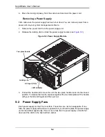
Insert a replacement unit into the empty power bay with the handle to the left.
2.
Push unit all the way in until it is firmly seated.
3.
Push the handle back into the closed position until it clicks into the locked position.
Operating Conditions
Temp: -5 to 50 C
Humidity: 5 to 95% RH
Fan Type
4x 90mm fans
- PFB0912DHE-6X39
(8000 RPM)
- QFR0912UHE-6F78
(8300 RPM)
NOTE:
Refer to
www.supermicro/products/superblade
for possible updates on
part numbers.
WARNING:
This left/right orientation depends on the power supply’s top or
bottom location. If you inadvertently put a power supply upside down in the lower
slots, it can be VERY difficult to remove the power supply.
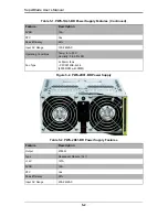
Table 5-2. PWS-2K01-BR Power Supply Features
Feature
Description
Содержание SuperBlade Series
Страница 1: ...SuperBlade User s Manual Revison 1 0c...
Страница 4: ...SuperBlade User s Manual iv Notes...
Страница 8: ...SuperBlade User s Manual viii Notes...
Страница 10: ...SuperBlade User s Manual x Notes...
Страница 12: ...SuperBlade User s Manual xii Notes...
Страница 22: ...SuperBlade User s Manual 1 10 Notes...
Страница 30: ...SuperBlade User s Manual 3 6 Figure 3 4 Enclosure Installed into Rack...
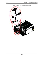
Страница 53: ...5 7 Chapter 5 Power Supply Modules Figure 5 6 Power Cable Tie and Clamp Assembly...
Страница 54: ...SuperBlade User s Manual 5 8 Notes...
Страница 58: ...SuperBlade User s Manual A 4 Notes...
Страница 64: ...SuperBlade User s Manual B 6 Notes...
Страница 66: ...SBI 7125B T1 Blade Module Main Manual...

