background image

19

NOTE: DIAGRAMS & ILLUSTRATIONS NOT TO SCALE.

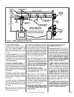
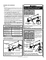
Horizontal / Inclined Run

Support Brackets

Building

Support

Framing

SV4.5E90

Elbow

Ceiling

u

 Firestop / Spacer

SV4.5VF

u

 When Using Secure Flex, 

Use Firestop / Spacer SF4.5VF

Fireplace

SV4.5L6/12/24/36/48

Vent Sections

Vertical

Rise

SV4.5HT-2

Termination

Shown

Support Bracket Spacing

Every 5 ft (1.52 m)

Exterior

Wall

SV4.5HT-2

Termination

Shown

Figure 31 - 

TYPICAL HORIZONTAL VENT INSTALLATION

See 

Figure 18 

on 

Page 14

 or 

Figure 21

 on 

Page 15 

 for vertical vent section support.

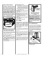
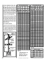
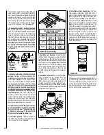
B.


Frame exterior wall opening -


Locate  the  center  of  the  vent  outlet  on 

the  exterior  wall  according  to  the  dimen-

sions shown in 

Figure 14 

on 

Page 11.

  Cut 

and/or  frame  an  opening,  10-1/2"  x  12-1/8"  

(267 mm x 308mm) inside dimensions, about 

this center. 

C.


Frame ceiling opening -

 If the vertical route 

is to penetrate a ceiling, use plumb line to locate 

the center above the appliance. Cut and/or frame 

an opening, 10-1/2" x 10-1/2" (267 mm x 267 

mm) inside dimensions, about this center (refer 

to 

Figure 19 

on 

Page 15

).

D.


Attach vent components to appliance - 

To 

attach a vent component to the appliance collar, 

align the dimpled end over the collar, adjust-

ing the radial alignment until the four locking 

dimples are aligned with the inlets of the four 

incline channels on the collar (

refer to Figure 

20


on 

Page 15).

Push  the  vent  component  against  the  collar 

until it fully engages, then twist the component 

clockwise, running the dimples down and along 

the incline channels until they seat at the end 

of the channels.

The  unitized  design  of  the 

Secure  Vent


components  will  engage  and  seal  both  the 

inner and outer pipe elements with the same 

procedure.  Sealant and securing screws are 

not required.

Note:

 An elbow may also be attached to the 

appliance collar.  Attach in the same manner 

as you would a vent section. 

E.


Attach  vent  components  to  each  other 

-

 Other vent sections may be added to the pre-

viously installed section in accordance with the 

requirements of the vent tables.  To add another 

vent component to a length of vent run, align the 

dimpled end of the component over the inclined 

channel end of the previously installed section, 

adjusting the radial alignment until the four lock-

ing dimples are aligned with the inlets of the four 

incline channels of the previous section.  

Push the vent component against the previous 

section  until  it  fully  engages,  then  twist  the 

component clockwise running the dimples down 

and along the incline channels until they seat at 

the end of the channels.

This seating position 

is indicated by the alignment of the arrow and 

dimple as shown in


Figure 20 on Page 15.

F.


Install firestop/spacer at ceiling - 

When using Secure Vent, use SV4.5VF firestop/

spacer at ceiling joists; when using Secure Flex, 

use SF4.5VF firestop/spacer. 

If there is living space above the ceiling level, 

the firestop/ spacer must be installed on the 

bottom  side  of  the  ceiling.  If  attic  space  is 

above the ceiling, the firestop/ spacer must be 

installed on the top side of the joist. Route the 

vent sections through the framed opening and 

secure the firestop/spacer with 8d nails or other 

appropriate fasteners at each corner.

Remember to maintain 1" (25 mm) clearance 

to combustibles, framing members, and attic 

or  ceiling  insulation  when  running  vertical 

chimney sections

.

G.


Support the vertical run sections - 

See 

Section E

 on 

Page 15.

H.


Change vent direction  -

 At transition from or 

to a horizontal/inclined run, install the SV4.5E45 

and SV4.5E90 elbows in the same manner as 

the straight vent sections.  The elbows feature a 

twist section to allow them to be routed about the 

center axis of their initial collar section to align 

with the required direction of the next vent run 

element. 

Twist elbow sections in a clockwise 

direction only so as to avoid the possiblity of 

unlocking any of the previously connected vent 

sections.

 See 

Figure 22 on Page 16

.

I.


Continue installation of horizontal/inclined 

sections -

  Continue with the installation of the 

straight vent sections in horizontal/inclined run 

as described in 

Step E

. Install support straps 

every 5 ft. (1.52 m) along horizontal/inclined 

vent runs using conventional plumber’s tape. 

See 

Figure 31.


It is very important that the 

horizontal/inclined  run  be  maintained  in  a 

straight (no dips) 

and recommended to be in 

a slightly elevated plane, in a direction away 

from the fireplace of 1/4" rise per foot (20 mm 

per meter) which is ideal, though rise per foot 

run ratios that are smaller are acceptable all 

the way down to at or near level.

It is important to maintain the required clear-

ances to combustibles: 1" (25 mm) at all sides 

for all vertical runs; and 3" (76 mm) at the top, 

1" (25 mm) at sides, and 1" (25 mm) at the 

bottom for all horizontal/inclined runs.

Содержание SSDV-3328

Страница 1: ... Follow your gas suppliers instructions If your gas supplier cannot be reached call the fire department Installation and service must be performed by a qualified installer service agency or the gas supplier WARNING IFTHEINFORMATIONINTHISMANUAL IS NOT FOLLOWED EXACTLY A FIRE OR EXPLO SIONMAYRESULTCAUSINGPROPERTYDAMAGE PERSONAL INJURY OR LOSS OF LIFE POUR VOTRE SÉCURITÉ Ne pas entreposer ni utiliser...

Страница 2: ...owner s manual installation instructions and war ranty envelope is located in the control compartment 3 One vent restrictor to be applied as shown on Page 13 restrictor is taped to the envelope 4 One hood located behind the top panel 5 Onebagofdecorativevolcanicstonelocated in the control compartment 6 One bag of glowing embers located in the control compartment This appliance is only for use with...

Страница 3: ...olt models Fuel Low High Natural Gas Lo 2 2 WC 55 kPa Hi 3 5 WC 87 kPa Propane Lo 6 3 WC 1 57 kPa Hi 10 0 WC 2 49 kPa Table 4 Test gauge connections are provided on the front of the millivolt gas control valve identi fied IN for the inlet and OUT for the manifold side A 1 8 NPT Test gauge connection is provided at the inlet and outlet side of the electronic gas control valve Burner Orifice Sizes E...

Страница 4: ...ector must comply with NFPA 720 be ANSI UL 2034 listed and be IAS certified A metal or plastic identification plate must be permanently mounted to the exterior of the building at a minimum height of eight 8 feet above grade and be directly in line with the horizontal termination The sign must read in print size no less than one half 1 2 inch in size GAS VENT DIRECTLY BE LOW KEEP CLEAR OF ALL OBSTR...

Страница 5: ... temperatures see Figure 4 The location should also be free of electrical plumbing or other heating air conditioning ducting These direct vent appliances are uniquely suited for installations requiring a utility shelf positioned directly above the fireplace Utility shelveslikethesearecommonlyusedforlocat ing television sets and decorative plants Be aware that this is a heat producing appliance Obj...

Страница 6: ...erican National StandardforManufacturedHomes NCSBCS ANSI A225 1 latest edition CAUTIONS Ensure that the cross members are not cut or weakened during installation Thestructuralinteg rity of the manufactured home floor wall andceiling roofmust be maintained Thisappliancemustbegrounded to the chassis of the manufac tured home in accordance with local codes or in the absence of local codes with the Na...

Страница 7: ...ions exceeding 2 1 2 64 mm see Figure 6 All horizontal terminations may be located as close as 6 152mm to any combustible exterior sidewall This distance may be decreased to 2 51mm if the SV4 5HT 2 or SF4 5HT 2 termination is used and the exterior sidewall is non combustible only For additional vent location restrictions refer to Figure 7 on Page 8 Termination Heights For Vents Above Flat Or Slope...

Страница 8: ... h t i w m c 1 9 t e e f 3 y l b m e s s a r o t a l u g e r r e t e m e h t e v o b a t e e f 5 1 f o t h g i e h a n i h t i w m c 1 9 t e e f 3 y l b m e s s a r o t a l u g e r r e t e m e h t e v o b a t e l t u o t n e v r o t a l u g e r e c i v r e s o t e c n a r a e l C I m c 1 9 t e e f 3 m c 1 9 t e e f 3 r o g n i d l i u b o t t e l n i y l p p u s r i a l a c i n a h c e m n o n o t...

Страница 9: ...um side wall clearance a combustible wall can project to any length Protected wall shown in white Inches millimeters Figure 10 At 8 1 4 side wall clearance a combustible wall can project 12 Hood Mantel Depth 4 102 2 51 4 102 6 152 8 203 10 254 12 305 6 152 10 254 14 356 12 305 8 203 5 127 8 1 4 209 14 356 12 305 19 483 45 o MINIMUM CLEARANCES Inches millimeters Back 1 2 13 0 0 Spacers Sides 1 2 13...

Страница 10: ...provided and bringinelectricalservicelineforforcedair circulating blower optional equipment b ElectronicAppliances Fieldwireandinstall operating control switch Step 5 Page 25 Install blower kit optional equipment Step 6 Page 26 Make connection to gas sup ply Step 7 Page 27 Checkout appliance operation Step 8 Page 28 Install the logs decorative volcanic stone and glowing embers Step 9 Page 30 Insta...

Страница 11: ...dels only ELECTRICAL INLET 2 3 4 x 2 70 x 51 COVER PLATE with KNOCKOUT Right Side View SSDVR models have only a rear vent SSDVT models have only a top vent 6 13 16 173 2 3 4 70 33 1 8 841 30 1 8 765 27 1 2 699 17 432 19 5 8 498 10 3 4 273 33 1 8 841 Inches millimeters 1 25 1 25 Notes Due to Lennox ongoing commitment to quality all specifications ratings and dimensions are subject to change without...

Страница 12: ...ver use galvanized or plastic pipe Refer to Table 9 for proper sizing of the gas supply line if black iron pipe is being used Gas lines must be routed constructed and made of materials that are in strict accordance with local codes and regulations We recommend that a quali fied individual such as a plumber or gas fitter be hired to correctly size and route the gas supply line to the appliance Inst...

Страница 13: ...he vent pipe is tested to be run inside an enclosing wall such as a chase There is no requirement for inspection openings in the enclosing wall at any of the joints in the vent pipe WARNING Failure to reinstall and securely tighten cover plate screws could result in leakage of flue products into the living space Vent cover plate and vent seal plate must remain securely installed on unused vent col...

Страница 14: ... 5 1 3 5 2 6 2 0 3 0 0 0 3 5 4 3 5 7 8 2 0 0 0 1 0 1 5 7 3 5 2 1 3 1 1 1 0 0 3 5 3 4 5 2 6 3 0 2 1 0 0 3 5 4 5 7 3 0 0 2 0 0 2 5 6 4 5 7 8 3 0 0 0 0 1 1 5 9 4 5 2 1 4 1 0 2 0 0 3 1 5 5 2 4 1 0 0 0 1 2 5 5 5 5 2 6 4 0 1 2 0 0 3 7 5 5 7 4 0 0 1 1 0 2 6 6 5 2 5 0 2 2 0 0 4 5 7 6 5 2 6 5 0 0 3 0 0 3 9 6 5 7 5 0 0 0 2 0 2 2 7 6 1 0 3 0 0 4 5 3 7 5 2 1 6 1 0 0 2 0 3 5 9 7 5 2 6 6 0 1 0 2 0 3 1 8 5 7 6 0...

Страница 15: ...nselectinglengthcombinations Elbowsare available in 90 and 45 configurations Refer to Figure 22 on Page 16 for the SV4 5E45 and SV4 5E90 elbow dimensional specifications Where required a telescopic vent section SV4 5LA may be used to provide the installer withanoptionininstallingintightand confined spaces or where the vent run made up of fixed length pieces develops a joint in a undesirable locati...

Страница 16: ... the center axis of their initial collar section to align with the required direction of the next vent run element Twist elbow sections in a clockwise direction only so as to avoid the possiblity of unlocking anyofthepreviouslyconnectedventsections See Figure 22 K Install the vertical termination The final step involves installation of the SV4 5CGV 1 Vertical Termination Extend the vent sections t...

Страница 17: ...ingSecureFlex useFirestop Spacer SF4 5VF uCeiling Firestop Spacer SV4 5VF uCeiling Firestop Spacer SV4 5VF vWall Firestop Spacer SV4 5HF uWhen using Secure Flex use Firestop Spacer SF4 5VF vWhen using Secure Flex use Firestop Spacer SF4 5HF Table A H Maximum V Minimum feet meter feet meter 2 0 610 1 0 305 4 1 219 2 0 610 6 1 829 3 0 914 8 2 438 4 1 219 V H 40 feet 12 2 meters Max H 8 feet 2 4 mete...

Страница 18: ...Flex useFirestop SpacerSF4 5HF Figure 29 Rear Vent three elbows Figure 30 Top Vent three elbows VERTICAL VENT FIGURES TABLES CONTINUED Horizontal Outside Wall Termination System Figure 31 and Figures 34 to 40 on Pages 21 to 23 and their associated Horizontal Vent Table illustrate the various horizontal venting configurations that are possible for use with theseappliances SecureVentpipeapplications...

Страница 19: ...nels of the previous section Push the vent component against the previous section until it fully engages then twist the componentclockwiserunningthedimplesdown and along the incline channels until they seat at the end of the channels This seating position is indicated by the alignment of the arrow and dimple as shown in Figure 20 on Page 15 F Install firestop spacer at ceiling WhenusingSecureVent ...

Страница 20: ... 5HT 2 Termination J Assemble vent run to exterior wall If not previously measured locate the center of the vent at the exterior wall Prepare an opening as described in Step B Assemble the vent system topointwheretheterminusofthelastsectionis located relative to the exterior surface to which the termination is to be attached see Figures 32 33 and Table 12 on Page 21 If the terminus of the last sec...

Страница 21: ...ACCEPTABLE AS 1 FOOT OF VERTICAL RISE EXCEPT WHERE AN ELBOW IS THE ONLY VERTICAL COMPONENT IN THE SYSTEM See Figure 35 See Table 12 as an aid in venting component selection for a particular range of exterior wall thicknesses WARNING Under no circumstances may separate sections of concentric flexible vent pipe be joined together HORIZONTAL VENT FIGURES TABLES Figure 36 Top Vent ONE 90 DEGREE ELBOW ...

Страница 22: ...See Table 12 on Page 21 as an aid in venting component selection for a particular range of exterior wall thicknesses HORIZONTAL VENT FIGURES TABLES CONTINUED Table H H H1 Maximum HMaximum V Minimum feet meter feet meter feet meter 5 1 524 2 0 610 1 0 305 10 3 048 4 1 219 2 0 610 15 4 572 6 1 829 3 0 914 20 6 096 8 2 438 4 1 219 V H H1 40feet 12 2m Max H 8 feet 2 438 meters Max H H1 20 feet 6 096 m...

Страница 23: ...t of horizontal run up to a maximum total H H1 H2 horizontal run of 20 feet Figure 40 Top Vent THREE 90 DEGREE ELBOWS Figure 39 Rear Vent THREE 90 DEGREE ELBOWS See Table 12 on Page 21 as an aid in venting component selection for aparticularrangeofexte rior wall thicknesses See Table 12 on Page 21 as an aid in venting component selection for a particular range of exterior wall thicknesses HORIZONT...

Страница 24: ...ovideadditional security to the connection B Install the Outer Flex Pipe 1 Install the large gear clamp loosely around the outer flexible vent pipe push it back out of the way 2 ApplyabeadofMill PacBlack 700 F high temperature sealant Catalog No 10K81 to the outer adapter collar to the grooves of the collar which extend approximately 1 inch from the end and to the flat surface approximately 1 3 4 ...

Страница 25: ...trical power must be connectedtoeitherofthesereceptaclesinorder to operate these blowers Install the blower kits according to the installation instructions provided with the kits 3 Wire the control within the millivolt control circuit using the 15 feet of 2 conductor wire supplied with the unit Caution do not connect the optional wall switch to a 120V power supply 4 Alternatively theappliancemaybe...

Страница 26: ...cal codes the National Electrical Code ANSI NFPA 70 latest edition In Canada the current CSA C22 1 Canadian Electrical Code Step 6 Connecting Gas Line Make gas line connections All codes require a shut offvalvemountedinthesupplyline Figure 46 illustrates two methods for connecting the gas supply The flex line method is acceptable in the U S however Canadian requirements vary depending on locality ...

Страница 27: ... Appliance Opera tion With the gas line installed run initial system checkout before closing up the front of the appliance Follow the pilot lighting instructions provided in the Homeowner s Care and Opera tion Instructions For piezo igniter location see Figure 48 millivolt appliances only Note The pull out Lightinginstructionslabel can be found in the control compartment see Figure 47 When first l...

Страница 28: ... edge of the ember bracket 4 Insert the alignment hole of the right twig over the front log s right pin Rotate the right twig until it almost touches the front panel glass Note Propertwigplacementiscriticalinthe gapsbetweentheflamepeaksandshouldbe positioned so that at no time they impinge the flames Glowing Ember Volcanic Stone Placement Remove the replacement rockwool Glowing Embers from the pac...

Страница 29: ...Volcanic Stone Table 13 Bag of Glowing Embers rockwool Separate into Quarter Size separate Pieces WARNING DONOTattempttoinstallthelogs until the appliance installation hasbeencompleted thegasline connected and tested for leaks and the initial burner operation has been checked out Figure 53 Glowing Embers WARNING This appliance is not designed to burn wood Any attempt to do so could cause irreparab...

Страница 30: ... The glass door of this appli ance must only be replaced as a complete unit as provided by themanufacturer Donotattempt to replace broken cracked or chipped glass separately WARNING Do not attempt to touch the front enclosure glass with your hands while the fireplace is in use Air Shutter Adjustment Guidelines If there is smoke or soot present first check the log set positioning to ensure that the...

Страница 31: ...See Page 6 for Cold Climate Insulation and Page 9 for Clearances Burner Air Shutter Adjustment Procedure CAUTION Theairshutterdoorandnearbyappliancesurfacesare hot Exercise caution to avoid injury while adjusting flame appearance Burner Air Shutter Adjustment Procedure 1 Locate adjustment rod and adjust air shutter to the standard setting as shown in Figure 56 adjustment rod is located in the lowe...

Страница 32: ...7 1 2 effective length 4 77L76 SV4 5E45 45 Degree Elbow 5 77L77 SV4 5E90 90 Degree Elbow 3 4 5 6 7 10 1 8 9 11 Installation Accessories The following flashings come packaged with a storm collar 6 77L78 SV4 5F Flat Roof Flashing 6 77L79 SV4 5FA 1 2 to 7 12 Adjustable Flashing 6 77L80 SV4 5FB 7 2 to 12 12 Adjustable Flashing 7 77L81 SV4 5SC6 Storm Collar 6 per box 8 H2246 SV4 5HF Firestop Spacer Hor...

Страница 33: ...SFMP 12 Mill Pac Black High Temperature Sealant Bulk 12 pack 23 91L66 SF GC4 6 Gear Clamp 4 5 in 114 mm for flex 6 pieces 23 91L67 SF GC7 6 Gear Clamp 7 5 in 190 5 mm for flex 6 pieces 24 99L02 SV4 5HRK14 Horizontal Riser Kit 14 24 99L03 SV4 5HRK36 Horizontal Riser Kit 36 25 H1988 CTSA 33 Chase Top Shroud Kit Arch Top 3 X 3 26 H1985 CTSO 33 Chase Top Shroud Kit Open Top 3 X 3 26 H1987 CTSO 44 Chas...

Страница 34: ...structionssuppliedwiththekit The qualified service agency performing thisinstallationassumesresponsibil ity for this conversion AVERTISSEMENT Cet équipement de conversion sera installé par une agence qualifiée de service conformément aux instruc tionsdufabricantettoutesexigences et codes applicables de l autorisés avoir la juridiction Si l information danscetteinstructionn estpassuivie exactement ...

Страница 35: ...ning it clockwise Replace the plastic protecting cap Pilot for Honeywell Millivolt Gas Valve Loosening of Hex Fitting For Orifice Strip Tab Positioning Figure 62 7 16 in Open End Wrench Hood Hood Alignment Orifice Strip Tab Take care not to contact the orifice strip tab with the hex fitting wrench distortion of the tab may render the pilot inoperative LP propane Gas Posi tion 1 16 inch hole LP and...

Страница 36: ...the kit See Table 14 for orifice sizes required for use with natural gas or propane gas Figure 65 illustrated the orifice Step 6 Electronic Appliances Honeywell Systems See Figure 63 and the instructions provided with the kit Remove the slotted cap screw o ring pressure regulating adjusting screw and spring Retain all parts for possible later use Install new components from the kit Black cap and r...

Отзывы: