11
NOTE: DIAGRAMS & ILLUSTRATIONS NOT TO SCALE.
FIREPLACE SPECIFICATIONS
Vent Size
Co-axial DV Vent Size
4-1/2" Inner
7-1/2" Outer
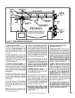
Vertical Venting Through the Ceiling:
Frame ceiling opening
-
Use a plumb
line from the ceiling above the appli-
ance to locate center of the vertical run.
Cut and/or frame an opening, 10-1/2"
x 10-1/2" (267 mm x 267 mm) inside
dimensions, about this center mark
(see
Figure 19)
.
21-1/2
(546)
13
(330)
1/2 (13)
1-5/8
(42)
8-11/32
(212)
3 (76)
Top View
NOTE - Eyebrow
hood shown as positioned
in louvered front model.
*CONCENTRIC FLUE
FLUE - 4-1/2 (114)
COMBUSTION AIR - 7-1/2
FRAMING
SPACERS
(Top and Sides
and Rear)
GAS INLET
(Either Side
and bottom)
Front View
3 (76)
**Rear vent models only
ELECTRICAL INLET
2-3/4 x 2 (70 x 51)
COVER PLATE with
KNOCKOUT)
Right Side View
*SSDVR models have only a rear vent
*SSDVT models have only a top vent
6-13/16
(173)
2-3/4
(70)
33-1/8
(841)
30-1/8
(765)
27-1/2
(699)
17
(432)
**19-5/8
(498)
10-3/4
(273)
33-1/8
(841)
Inches (millimeters)
1 (25)
1
(25)
Notes
Due to Lennox' ongoing commitment to quality,
all specifications, ratings and dimensions are
subject to change without notice.
7
(178)
5-1/8
12-1/8
(308)
10-1/2
(
267
)
VENT FRAMING -
TOP VENT WITH ONE
90¡ ELBOW
VENT FRAMING -
REAR VENT WITH
NO ELBOWS
Framing should be constructed
of 2 x 4 or larger lumber.
Inches (mm)
(130)
7
(178)
*12-7/8 inches (327 mm) is the
required framing depth dimension
when the finish material (drywall)
thickness is 1/2 in. (13mm).
*12-7/8
(327)
33-1/4
(845)
33-1/4
(845)
16-5/8
(422)
37-1/8
(943)
19-5/8
(498)
FRAMING WITH SQUARE HORIZONTAL TERMINATION (SV4.5HT-2)
5-1/8
(130)
12-1/8
(308)
Figure 14


