background image

86

Last, input the code to set up end of 

sewing data setup speed. Input
method is same as 

Step4

of the first

input method.

You can set up sewing data speed with
the same method as described above.
Except, 

you should note that you can

have problem if you set up sewing data
speed in the range of the section that
speed was already setup. Please avoid
such setup.

You can apply this between design and
design in other pattern.

When you set up speed, please make
sure that you should set up on the
basis of sewing sequence. If not, error
message shall appear.

The method to apply in the section other than already sewing data speed setting
was applied.

press 

left button of mouse

beg-

inning with sewing data speed setting
location in order to set up sewing data
speed. 

The selected point 

changes into

red. Next, if you press right button of
mouse, the letter 

Spend

in blue shall 

appear. But, input is made without any
change because it exists already.

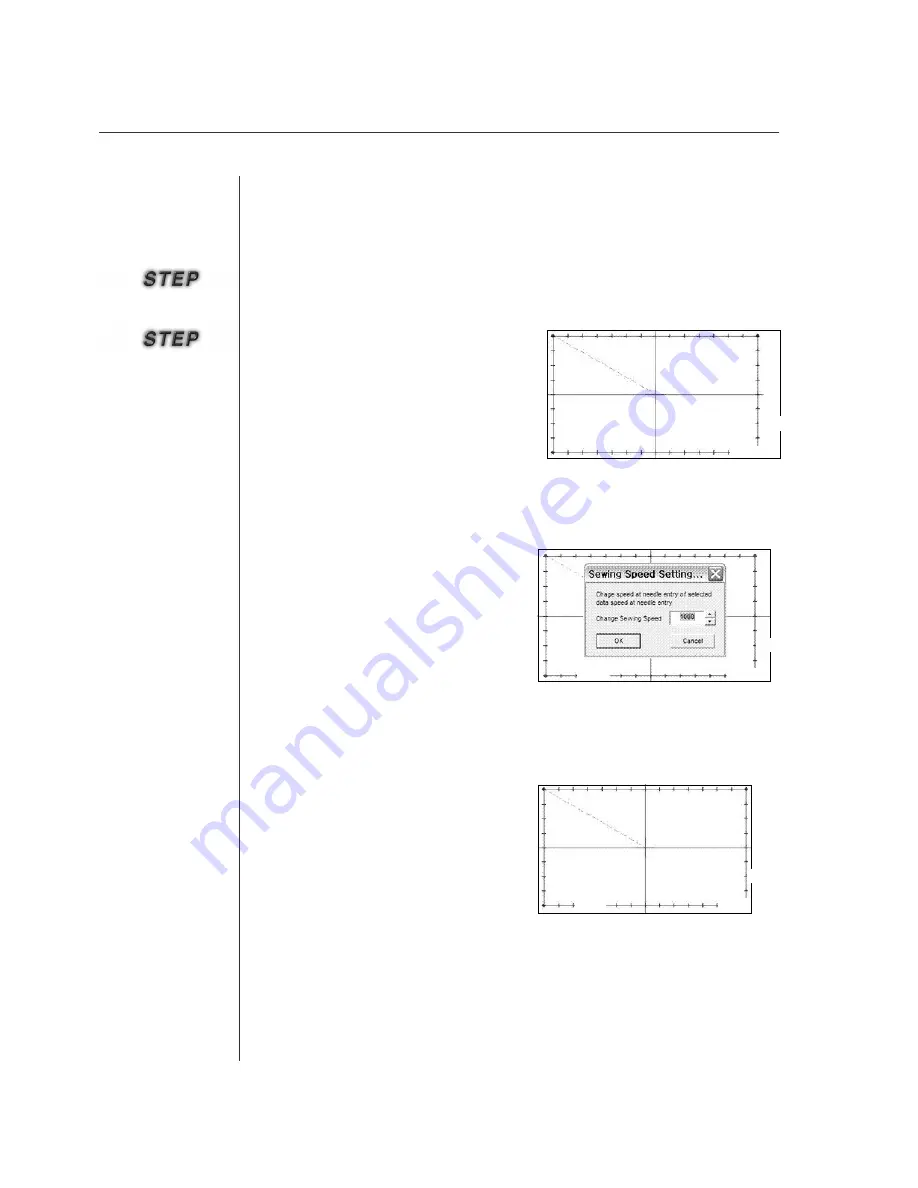
You can set up again taking the location that sewing data speed setting was ended for
the start point with the same method applied at first. 

Press 

Sewing Speed Setting

in the left Sewing Editing Tool Bar. The selected

button enters dented.

The method to start sewing data speed setting again at the end location of already
applied sewing data speed setting 

Spend

Spend

Spend

Spend

Spend

Spend

Spend

Spend

Spend

Содержание SSP-WE/3.5

Страница 1: ...SSP WE 3 5 IInstruction M Manual SSP WE 3 5 MEE 070418 ...

Страница 2: ......

Страница 3: ... functions high performance powerful operation enhanced durability and more sophisticated design to meet a number of user s needs 2 Please read this user s manual thoroughly before using the machine Make sure to properly use the machine to enjoy its full performance 3 The specifications of the machine are subject to change aimed to enhance product performance without prior notice 4 This product is...

Страница 4: ... Sewing Data 35 6 Selection of Elements with the Mouse 36 5 Create Data 37 1 New Pattern Creation 38 2 Creating Configuration and Sewing Data 39 Creating Configuration Data 39 Creating Sewing Data 42 Creating Mechanical Control Commands 47 6 Edit Function 65 1 Editing Configuration Data 66 Editing with the Mouse Point 66 Editing with the keyboard direction key Add Delete Move 68 Editing with the k...

Страница 5: ...erial Transmission 122 1 PC and KM 2070P connection configuration 123 2 Zigzag design direct transmission 125 3 ROM data serial transmission 127 ROM data serial transmission 127 Sample design Basic patterns for KM 2070P 128 10 Design transmission for bar tack series 129 1 Configuration flow between PC and bartack machine 130 2 Setting port and communication speed 131 3 Design direct transmission 1...

Страница 6: ...6 Before Using Check the followings prior to setting up the program and components ...

Страница 7: ...7 Principal Parts PC Print Port Interface cable Power Adaptor ROM Writer SSP Writer1 or USB Key Lock Key Lock ...

Страница 8: ...t No 01 008A WE10 7 AC Adaptor Part No 01 010A WE10 110V 01 011A WE10 220V 8 Extension ROM 10 Units Part No 02 003B BD01 9 ROM Extractor Part No 01 012A WE10 4 RS 232C Serial Cable Part No 02 012A 2070 5 USB to RS 232C conversion cable Part No 02 012A 2070 2 Instruction Manual 3 Key Lock for USB port Part No EP 000043 or Economic type Full type Manual ...

Страница 9: ...k of the key lock connected with the print port The key lock and the interface connection cable are configured with a separateshap ed pin to the both sides Please connect them with the same shaped pin Connect the interface cable with th SSP Writer1 connection port Connect the AC adapter with the SSP Writer1 Put a plug of AC adapter in a socket After completion of all connections power on the PC Co...

Страница 10: ...ws 98 or more Insert the CD and go to the Disk1 folder for installation by language Double click the Setup file in the folder Upon displaying InstallShield click Next Installing the Program Unavailable for Windows 95 Installing the Software ...

Страница 11: ...e Software License Agreement screen opens click Yes The Choose Destination Location screen opens If you want to change where to save click Browse and select another folder And click Next for the following process ...

Страница 12: ...k Finish to complete Setup You can find that the installed program is registered on the Start Menu Then Installation is successfully completed If you execute the program immediately after its installation it is not executed and only the message finding Key Lock is displayed Therefore connect Key Lock Driver and Key Lock before execution Note In SunStar SSP folder you will see that program related ...

Страница 13: ...1 0 exe for installation If the key lock drive for print port has already been installed this should be uninstalled before installing the above file Reboot the PC If a user has installed Service Pack 2 of Microsoft and the firewall is in operation the firewall should be turned off After following the above procedures execute SSP and then the program will be executed without any problems If the key...

Страница 14: ...c sewing machine input program relating to Pattern Bartack and KM 2070P that users can easily create and edit and manage sewing data generally covering about how to install and use the program Please recommend users that they should read through this manual without fail prior to using ...

Страница 15: ...egistered as shown in the Figure or click the execution file in the folder which is actually installed then you can execute the program To plug out the Key Lock during execution of the program occurs an Erro message in a few seconds and the program is not executed Therefore do not plug out the Key Lock during execution of the program Please without fail to save sewing data prior to terminating the...

Страница 16: ...scribes how to create and edit configuration data or sewing data using keyboard direction keys Before using you must read though the screen mode The program is set up to automatically configure its screen size according to your monitor size If you change the default screen size and execute the program to input and edit data using keyboard direction keys it is not changed normally because of its ma...

Страница 17: ...restrain from reducing the screen excessiv ely Select configuration data or sewing data to be applied prior to executing each function Upon selecting data the configuration data indicates in blue and the sewing data indicates in red If you want to execute any data it is good that you select it with a mouse and apply it although the blue or the red indicates ...

Страница 18: ...18 Configuration of Program Function ...

Страница 19: ...ined by the sewing range determine the edit range and are symmetrica lly displayed on the center of the screen Select a sewing size by sewing machine types and models Determine sewing size Set up various default values for sewing and set up them again according to usage Input configuration data to create sewing data Edit the created configuration and sewing data again Set up the length and width o...

Страница 20: ... and there are various functions including them Initial Sewing Parameter Input Screen Start Screen Machine Model Setup Screen Edit Screen Program Finish Ron Wrster Send design data serial Image Punching Embroidery Conversior CAD dxf file Conversior M C In Out Port Control Input Pitch Width Input Back Tack Input Machine Command Save Data ...

Страница 21: ...nu Bar or Sub Tool Bar or Tool Bar a message is displayed on the Status Bar to tell you the next process Click the left button of the mouse according to the message and input data on the edit screen Create or edit sewing data according to the execution status of the Dialog Box Menu Bar Sub Tool Bar Edit Screen Tool Bar Mechanical Sub Tool Origin Stauts Bar Edit Size Frame ...

Страница 22: ...r Dialog Control Bar Dialog Stitch point ON OFF Zoom In Zoom Out Zoom Full Client Imformation Display element Display element Stitch Replay Min Max Range Grid Division Setting Mesure Point to Point Ruler Input device Key input Key input Add Move Keyboard resolution Select User P C Condition setting Set sewing area Set sewing data selection scope Lay out stitch points Machine type Mechine type mode...

Страница 23: ...nication Send 2070P design Send bartack design Send pattern design Start new pattern Read a saved pattern data file Save pattern data on the edit screen Save 2070P zigzag design cord list value Covert Pattern into Bartack Set port and speed for serial transmission Send newly created design direct Send newly created design direct Send newly created design direct ROM Execute SSP Writer program Redo ...

Страница 24: ... Rotate the selected pattern data Inversely rotate the selected pattern data Hide all stitch points on the screen Display again all hidden stitch points on the screen Measure the distance between two stitches Show the selected configuration and sewing data information 2 Step Stitch Create a stitch between stitches First Pointer Previous Pointer Next Pointer Last Pointer Select the first data group...

Страница 25: ...e editing screen F2 Key When converting to the automatic point in the grid line the point is input on the location where the lines are automatically overlapped upon inputting the point Sewing Command Tool Bar T To ot ta al l S St ti it tc ch h Display the number of Stitch Points displayed on the screen A Ab bs so ol lu ut te e R Re el la at ti iv ve e Display the inputted absolut relative coordina...

Страница 26: ...ion to enlarge or reduce the current sewing range and move the enlarged range freely using Hand Tool And provide the Ruler function Not be currently provided But this will be applied in the Upgrade Version to display a ruler to the left and upper of the screen that users can find the size easily and the Grid Line function for a user to easily input data by displaying the sewing range with the grid...

Страница 27: ...Move one point of configuration data Divide the selected configuration data on the basis of joints Position and create configuration data in a constant interval Data Delete the selected configuration data This is a tool bar which have functions to actually create sewing data based on the configuration data input above Point Stitching to input stitch by stitch Normal Stitching to create general sew...

Страница 28: ... this is actually applied to sewing data To input and delete sewing data and to move stitches are the same concept as configuration data Stitch Point Join is the function to connect the Jump interval between two point stitches Add Sewing Speed Not be currently provided This will be provided in the Upgrade Version to set up the sewing data speed and Sewing Data Divide to select and divide any posit...

Страница 29: ...es more stitches based on the defined number of stitches Overlap defines the number of stitches based on the created sewing data and creates more stitches based the defined number of stitches based on the ending point of creation According the ending point of sewing data is created again to that of the number of added stitches Sewing Change Tool Sewing Direction Change Sewing Order Change Sewing A...

Страница 30: ...ol Command Input the delay time code from the selected sewing data Head Up Down Control Command Input the head up down code from the selected sewing data Pressure Foot Control Command Input the pressure foot control command into selected sewing data Clamp Motor Control Command Input the clamp motor control command into the selected sewing data This includes mechanical control commands Second Origi...

Страница 31: ...31 Data Configuration ...

Страница 32: ...ewing data created by configuration data The followings show data types simply Edit Frame Size Edit Frame Size Mechanical Control Data Creation Picture Jump Jump Point Sewing Stitching Machine Control Command Stop Y Shaft X Shaft Y Shaft Coordinate Origin Command Trim Configuration Spline Data Normal Arc Sewing Stitching Configuration Arc Data ZigZag Circle Sewing Stitching Configuration Circle Da...

Страница 33: ...d input the configuration data on the sewing range the configuration data indicates with a blue dotted line If you create another configuration data the previously created configuration data gets changed in gray and the currently creating configuration data gets changed in blue again As shown in the above Data Creation Picture the line in the blue part indicates the currently selected configuratio...

Страница 34: ...ated based on configura tion data creates a Spline of configuration data as shown in the above picture and creates zigzag stitching of sewing data with the Spline Third Mechanical Control Commands indicate commands such as the second origin temporary stop of machine thread trimm ing at any position of sewing data and clamp inversion noninversion These are indicated with text Stop for temporary sto...

Страница 35: ... is the sewing data is always created accord ing to the constant order and the configuration data is connected with the sewing data regardless of the order For example if four configuration data are created is the left picture it is assumed that the configuration data is numbered with 1 2 3 and 4 and the sewing data with 1 2 3 and 4 If you create sewing data with Configuration Data 4 Sewing Data 1...

Страница 36: ...button on the sub tool bar and click the button an item in the sub tool bar is concave like Select the data joint to configuration data and sewing data In case of sewing data each stitch data is selected The selected joint of configuration data is in circle shape and in blue like configuration data While sewing data is displayed in red and in black to display stitch data And configuration data and...

Страница 37: ...37 Create Data ...

Страница 38: ...the program Upon clicking all of two buttons the mechanical dialog box displays as shown in the left screen It has functions as follows Machine Type Select machine type to work Machine Model Set up machine model Sewing Size After the machine model is selected edit range sewing range is displayed Second it can be created by clicking New in the menu bar Upon clicking OK the edit range is changed int...

Страница 39: ...ion data of Spline is currently selected Therefore upon inputting continuously the input point displays on the screen Click the mouse s right button to finish inputting At that time Spline displays on the screen and the button concaved by selection in the tool bar beco mes reduced at original state Click Esc in the keyboard to cancel data under inputting This is not applied to any data created by ...

Страница 40: ...nput Polygon is same to that of Line However Polygon is a closed loop Therefore upon clicking the mouse s right button to finish inputting first point and last point are automatically connected The basic creation is same to that of Spline Upon the right button finally it is created absolutely identical with Polygon The following screen shows all configuration data created previously Input Arc Cric...

Страница 41: ...s set up to 10 pixels move unit becomes 1mm As mentioned above however this is possible only when the window screen keeps initial setup values The above Window Resolution indicates Monitor Resolution This is autom atically set up Therefore you don t need to change it Click the mouse s right button to finish inputting End key right over the keyboard s direct ion cursor also has the same function as...

Страница 42: ... left sewing toolbar When selected it remains pressed Place the mouse button at the desired location and press the mouse button to generate a jump code Whenever the left mouse button is pressed the jump structure data is drawn To cancel in the middle of drawing press Esc After finishing Step 2 press the right mouse button to generate a jump stitch When the button is pressed the jump generation win...

Страница 43: ... Delete the location data from the stitch data Use the stitch point deletion function to delete Undo function In the middle of work the function enables return again returned execution by undo function to the next status It can be used by pressing the REDO button on the top or simultaneously press Ctrl Y keys on the keyboard The Redo function can be used 20 times Follow the Steps below to use the ...

Страница 44: ...on key and numeral key Select Point Stitching button as showing in the figu re At this time the button becomes concave Put Mouse Point on the edit range to click the mouse s left button and input data You can continuously input data until finishing Point Stitching Click the mouse s right button to finish inputting The inputted Point Stitch data is displayed on the screen Point Stitching To return ...

Страница 45: ...n the left figure the selected configuration data displays in blue and the rest display in gray Click Normal Stitching in Sewing Tool Bar At this time Regular Stitch Dialog is displayed Data can be inputted in two places Stitch Length pitch to set up the length of stitch to be created and Sewing Speed to adjust the sewing speed at a user s disposal Please refer to that Sewing Speed is to be availa...

Страница 46: ...igzag stitches And there is a Speed Input box not be currently provided The third is a speed related input box however this box is not applied yet In the next item Zigzag types are presented As can be seen in the picture there are 4 Zigzag types Left to the center Right to the center Upper right to the center Lower left to the center Each item contains the Zigzag staring direction and creation loc...

Страница 47: ...case of the latter upon inputting the second origin at a certain place the second origin is created at the first sewing data and Jump created based on the actual origin And a new Jump to connect both sides is automatically created The following shows how to create the second origin for the latter Sewing data should be created before creating mechanical control commands Please refer to Creating Sew...

Страница 48: ...ere Sewing Data is created click the mouse s left button Then the bold part is the enlarged part as shown in the figure And blue dots indicate selected joints Click the mouse s right button to display Thread Trim Command Dialog as shown in the figure Click OK to input a thread trimming command otherwise click Cancel The following shows a figure including the thread trimming commands which are disp...

Страница 49: ...box that asks you to delete it Like this whenever you exe cute machine control commands the message box is displayed And a message that asks you how to do is also displayed on the lower status bar The order is as follows Macine Stop Control Command Clamp Inversion Command Medchanical Control Command Deletion Click Delete Machine Control Command at Machine Tool Bar prior to deleting it then the sel...

Страница 50: ...cally added Write directory name and file name then click Save When pressing the Cancel button in stead of the Save button the created thread trimming command does not disappear it stays effective Click All Thread Trimming Command in Machine Tool Bar under the state that machine command is created then the selected button gets concaved This is to make you convenient Thread is automatically trimmed...

Страница 51: ...killed engineer take extra caution in using the function Follow the steps below to use the function Assume there is a square pattern design as below This is an exercise aimed to activate the linked pneumatic signals at Point A and Point B of the square User output port code Select the output port function button When selected the button remains pressed Select Point A as the desired output point Wh...

Страница 52: ... 7 OP5 0 OP5 1 OP5 2 OP5 3 OP5 4 OP5 5 OP5 6 OP6 0 OP6 1 OP6 2 OP6 3 OP6 4 OP6 5 OP6 6 OP6 7 Description Presser Foot PF Feeding Frame FF Thread Trimming TT Thread Hold TH Wiper Solenoid Feeding Frame Left Twostage Solenoid Reverse Device Solenoid Rear Feeding Frame For 5050 Tension Release For 5050 Pneumatic Output 24V Oil Control For 5050 Head Up Down For 5050 Pneumatic Output 24V Pneumatic Outp...

Страница 53: ...delay time at the position just before the output port is set LAST Set the delay time at the position just behind the output port is set BOTH Set the delay time at the position before and behind the output port is set In FIRST set the delay time at 200ms Then 200ms of time delay occurs before Head ascends Set Head Down at Point B using the same method In LAST set the time delay at 200ms The figure...

Страница 54: ...nction Follow the steps below to use the function Assume that there is a square pattern design as below When the input port setting was made at Point A of the square the sewing machine stops the sewing at Point A and when an external signal is input to the chosen input port the sewing machine resumes operation again Output Port Control Command Select the input port function button When selected it...

Страница 55: ...ting Input port setting User can set input port LOW Input signal is low HIGH Input signal is high Set HIGH for input port 4 3 The figure below shows the design when the input port is set The input port table above is applicable when the C SERIES I O board is used In the existing A B SERIES OP4 0 OP4 7 cannot be used In the C SERIES IP 4 2 cannot be used 143 HI ...

Страница 56: ...put code together to set the optimized motion Follow the steps below to use the function Assume that there is a square pattern design as below When time delay is set at Point A of the square the sewing machine will stop operation at Point A and resume operation after the set delay time passes Delay Time Control Command Select the time delay function button When selected the button remains pressed ...

Страница 57: ...ay setting dialogue window appears at the same time Select the delay time for setting The delay time can be set at the unit of 4ms Select 100 to set 400ms of time delay Press the OK button to enter time delay The figure below shows the design when time delay was set D 400 ...

Страница 58: ...er take extra care in using the function Follow the steps below to use the function Assume that there is a square pattern design as below This is an exercise aimed to operate the head up and head down at Point A and Point B of the square Head Up Down Control Command for C Series only B Select the Head Up Down function button When selected it remains pressed Select the stitch point located at the d...

Страница 59: ...LAST Time delay is set at the position just behind the output port is set BOTH Time delay is set at the position just before and behind the output port is set In FIRST set 200ms for time delay It means 200ms of time delay occurs before the head ascends The time delay can be set before and behind the position where Head Up Down is set The purpose of giving time delay for Head Up Down is to give sub...

Страница 60: ...60 The figure below shows the conditions applied when the output port is set Set Head Down at Point B using the same method In LAST set 200ms for time delay H UP H DN ...

Страница 61: ...n using this function if you are not a trained or skilled engineer Follow the steps below to use the function Assume that there is a square pattern as bellow This is an exercise aimed to control pressure foot height at POINT A and POINT B of the square Pressure foot Control Command for E Series only B Press the Pressure Foot Control Command button When the button is selected it becomes hollow Clic...

Страница 62: ...es only The range of control is from 0 0mm to 8 0mm by 0 1mm A sewing machine will move the pressure foot up as amount of 7 0mm at the stitch point A Originally pressure foot height is 0 0mm so the pressure foot height will be 7 0mm at the stitch point A And then it will move the pressure foot down as amount of 5 0mm at the stitch point B Therefore the pressure foot height will be 2 0mm at the sti...

Страница 63: ... of the sewing Take extra care in using this function if you are not a trained or skilled Engineer Follow the steps below to use the function Assume that there is a square pattern as below Press the clamp motor control command button and Set Clamp Mount Window will appear Clamp Motor Command for E Series only ...

Страница 64: ...t 10mm on Set Motor Position category The range of control is from 0mm to 20mm by1mm Select 2 Enable Click OK Button The pressure foot control command is applicable to E Series only The original height of clamp is 20mm for pattern sewing machine ...

Страница 65: ...yboard direction key and third keyboard input value Accordingly you can change the data and point of configuration data and sewing data using Insert Delete and Move functions Please attention that the edit function cannot be applied without configuration data and sewing data in the edit range ...

Страница 66: ... is selected The joint displays in red Move Mouse Point where to add and continuous ly click the mouse s left button Then the inputting data is added based on the initially selected joint Click the mouse s right button to finish working At this time the last point inputted to add is autom atically connected with the next point of the existing configuration data point Click configuration data with ...

Страница 67: ...guration data is deleted point to point Please compare it with the above figure Add configuration point Delete Configuration Point For configuration data without sewing data continue to work with the above created data For configuation Point Click Move Configuration Point at Tool Bar The selected button gets concaved Click a configuration data joint to move the select ed joint displays in red Move...

Страница 68: ...r instead of the mouse s left button and moving the mouse point with Keyboard Direction Key Use End Key to terminate instead of the mouse s right button Select the function button Insert Delete Move to edit in the tool bar Move Mouse Point on the edit range and click Keyboard Direction Key Upon clicking Up Down Left and Right keys you can find that the mouse point moves Make Mouse Point conformed ...

Страница 69: ...n in the figure is displayed on the Key Input Add Move Dialog box Input configuration data point coordinates to be added into the Key Input Add Move box Click Ok to add the inputte coordinates Add Configuration Point In order to perform editing select the Move Configuration Data Segment button from the tool bar Perform the steps from through used to Add Configuration Data Segm ent How to move conf...

Страница 70: ... the place to add and continuously click its left button You can find that input data is added based on the initially selected joint Click the mouse s right button to terminate At this time you can find that the last point inputted to add is automatically connected with the next point of the existing configuration data point In case of editing sewing data including configuration data you must know...

Страница 71: ...v ed as shown in the figure If it has been selected select the correspond ing sewing data stitch The data stitch is displ ayed in a red circle dot as follows This displays the magnifying screen The best sewing data creation method is to create configuration data or sewing data create and edit sewing data conforming to actual design types then designate various attributes of sewing data to make the...

Страница 72: ...ata select and click the function button of last point in the Replay Tool Bar You can find that the selected stitch has moved to the last point of the current sewing data Click the start point button in the Replay Tool Bar to move the stitch to the start point of the current sewing data Upon clicking the function button the point moves to the current sewing data as shown in the following figures I...

Страница 73: ...inally click the mouse s left button to move the current sewing data at any place The moved sewing data point indicates in the following figure To edit stitches with the Replay Tool bar is applied only to Move and Delete buttons This is equal to how to edit with the mouse And it is characterized that you can edit stitch data checking its creation order ...

Страница 74: ...74 Data Processing These are indispensable functions upon processing configuration data or sewing data ...

Страница 75: ...ol then it gets concaved Place Mouse Point on the edit range then you can find that there is a hand shaped icon Click and move the mouse s left button then you can find that the screen moves depending on its move Hand Zoom In is used to enlarge the screen Select Zoom In Place Mouse Point where to enlarge the edit range Zoom In Edit Tool Information Short Key HELP F1 Grid Line F2 Hand Tool F3 Zoom ...

Страница 76: ... in the mouse s left button the range with square dotted lines is depicted Release the mouse s left button under this state and then the range is enlarged Zoom Out is used to reduce the screen Select Zoom Out Place Mouse Point where to reduce the edit range Click the mouse s left button then the screen is reduced on the basis of the pressing point Zoom Out ...

Страница 77: ... displayed at the same size as the edit range Zoom All Grid is used to display the screen at the interval set up by you This is very useful for inputting or editing data The default is set up 2mm long and wide Select Grid Immediately upon selecting it the screen is again depicted at the interval of 2mm with a grid pattern Grid ...

Страница 78: ... location that grid line is crossed is automatically moved and input to the nearest crossing point The following figure shows the figure being input when setting grid line to automatic point and inputting the point at optional location When optional point was input the point can be moved into 4 directions from the location that optional point be input as shown in the left figure below The point is...

Страница 79: ... t to o G Gr ri id d function is equally applied You can change on the item Grid Division Setting located on the bottommost of the item View of menu item of line width change Also S Sn na ap p t to o G Gr ri id d function is applied when editing It is equally applied f fo or r c co on nf fi ig gu ur ra at ti io on n d da at ta a m mo ov ve em me en nt t a ad dd di it ti io on n o of f c co on nf f...

Страница 80: ...splayed There are three input boxed as follows a box to determine the configuration data creation interval a box to determine its creation direc tion and finally a box to determine the number of times Click OK upon completing all inputs You can find that configuration data is been creating Even when the user has generated a design directly using the OP Box with those pattern machines like SPS 1306...

Страница 81: ...ept sewing data It should be considered that Arc Stitching was an attribute of sewing data that existed in previous Arc configuration data However after deleting configuration data it is changed into Point Stitching This is used to re create sewing data reversely Reverse Stitching Sewing Tool Click configuration data Click a reverse Stitching function button to displ ay Reverse Stitch Dialog As sh...

Страница 82: ...rse Stitching mentioned above This does not create stitches reversely but can create several same types of sewing data Multi Sewing Select configuration data Select Multi Sewing to display Multi Sewing Dialog It has various input boxes Multi Sewing Offset to set up the creating interval Multi Sewing Offset Direction Number of Times of Creation and Sewing Type divided into Regular Stitch and Zigzag...

Страница 83: ...oups of point stitches The first one is Included Jump Join and the other one is Point Group Join 1 Select Incuded Jump Join and click OK button After that you can find that jump stitches between two groups of point stitches Point Stitching Join Select Point Stitching Join Select first Point Stitching Data Click the mouse s right button The message saying that the following sewing data should be se...

Страница 84: ...They are just connected with new point stitches When moving starting and ending points of the connected point stitches the jump is created again as they move If the connection is not made even after pressing the Yes button which occurs once in a while press ESC on the keyboard and then reapply it The first application process is as follows Press Sewing Speed Setting in Sewing Editing Tool Bar in t...

Страница 85: ...ected dented returns to original shape Input the speed to set up at Sewing Speed Change Value on the dialogue box User Sewing Data Speed Setting If you click arrow in the direction of upward downward speed is changed If you set up the speed press OK button Then dialogue box shall disappear and speed is setup If you cancel it all the speed mark such as Spend set up to sewing data shall disappear We...

Страница 86: ... the section other than already sewing data speed setting was applied press left button of mouse beg inning with sewing data speed setting location in order to set up sewing data speed The selected point changes into red Next if you press right button of mouse the letter Spend in blue shall appear But input is made without any change because it exists already You can set up again taking the locati...

Страница 87: ...mouse s right button Sewing Stitch Division Dialog is displayed Click OK then you can find that the selected sewing data has been divided Sewing Change Tool Change the sewing data creation direction reversely Sewing Direnction Change Select Sewing Direction Change Select sewing data to change Click the mouse s right button to display Change Sewing Direction Dialog ...

Страница 88: ...tatus bar is displayed Select the second sewing data to be changed Click the mouse s right button to display Sewing Order Change Dialog Click OK then you can find that the order of sewing data has been changed The sewing order should be selected conforming to that of the created sewing data That is if sewing data and and sewing data and are out of order the Order Change is not applied If the appli...

Страница 89: ...erefore select Zigzag Stitch Immediately click Zigzag Stitch Zigzag Dialog is displayed Input attribute values there Select OK then you can find that the sewing data attributes have been changed Sewing Length Change Select sewing data to be changed Select Sewing Length Change Sewing Length Change Zigzag Dialog is displa yed It includes two input boxes Zigzag Width and Zigzag Length The default is ...

Страница 90: ...e If point is selected Sewing Speed Setting Change dialogue box shall appear This shall automatically appear if speed setting mark is contained in the selected sewing point But if select the point not contained it shall not appear Click the Sewing Speed Change button in the item of sewing change tool bar Upon selecting it enters dented When changing sewing data needle speed Sewing Speed Setting Ch...

Страница 91: ...oth Third Insert ing Method determines how to input Back Tack whether to input one times or two times And Last Sewing Speed determines the sewing speed Not to be provided Select OK then you can find that Back Tack has been inserted into the existing sewing data However you cannot find that Back Tack has been input where and as much as you set up Therefore you can find by the figure through stitch ...

Страница 92: ...stitches You cannot that overlapping is successfully exe cuted because the stitches are overlapped Therefore the overlapping can be confirmed by moving the last overlapped stitch The following figure shows the overlapped status through stitch move Apply the Overlap function to the selected sewing data An overlap sewing function can be applied only to the sewing data created based on the following ...

Страница 93: ...sewing data without configuration data exist a Pattern All function is applicable However a reverse function is excluded Select Enlargement Reduction to display Enlarg ement Reduction Dialog As a dialogue box appears the selected configuration data or sewing data are shown in a dotted box simu ltaneously It has the following function Enlargement Reduction of specified elements range Applied to the...

Страница 94: ... Dialog The selected pattern is displayed to the whole range with dotted lines as shown in the figure The Rotation Dialog includes the following functions Rotation of whole pattern Rotate the whole pattern completely Rotation of Specified elements range Rotate only the selected configuration data or sewing data Angle Input the rotation angle No Origin or center Rotate based on the selected data Ye...

Страница 95: ...ation Move Select configuration and sewing data to move Select Move to display Move Dialog The sel ected pattern is displayed to the whole range with dotted lines as shown in the figure Move the selected configuration and sewing data The Move Dialog includes the following functions Parallel move of whole pattern Move the whole pattern completely Parallel move of Specified elements range Move just ...

Страница 96: ...ror to display Mirror Reflection Dialog It includes the following functions X axis Mirror based on X axis Y axis Mirror based on Y axis Point Set up any position of a user and mirror it This figure shows Mirror based on Y axis Click OK The selected pattern is displayed to the whole range with dotted lines as shown in the figure Immediately click the mouse s right button Mirror Point Dialog is disp...

Страница 97: ... Point to Point on the Measure tool bar The selected button gets conc aved Select the first sewing data joint to measure with the mouse s left button The selected joint shows in a dark circle as shown in the figure Continuously select the second joint It also shows in a dark circle as shown in the figure If the figure above is displayed click the mouse s right button The selected dark circle disap...

Страница 98: ...d stitch It can apply to all existing Zigzag or general stitch Application procedure is as described below In such case as above we applied 2 Step Stitch to ZigZag that has configuration data If you m mo ov ve e s se eg gm me en nt t o of f c co on nf fi ig gu ur ra at ti io on n d da at ta a y yo ou u c ca an n c cr re ea at te e Z Zi ig gZ Za ag g a ag ga ai in n a ac cc co or rd di in ng g t to...

Страница 99: ...design that he she already has saved Select User PC There is Select User PC in the bottom most of the item Input Device on top menu item And there are Notebook and Desk Top as the list of item Select User PC Initially Desk Top was setup as basic setup You may setup to Notebook from the item Desk Top If you input by using arrow key on keyboard after setting up the problem to go astray won t happen ...

Страница 100: ... shown in sewing setting dialog X is set at 130mm and Y at 60 mm The sewing area set in the initial display is aligned with these values Set X length at 70mmm and Y length at 50mm and click Ok then the sewing edit area will change as shown in the figure The area will change while sewing data remains the same The following figure shows Before and After setting the sewing edit area Before After ...

Страница 101: ...ing data will expand Just bring the mouse near the sewing data point and click to automatically select the sewing data Contrariwise carefully select the sewing data to reduce the value of this area Sewing point selection area The value of the sewing point selection area works similarly to sewing data selection area only that this function is designed to select the sewing point Increase the set up ...

Страница 102: ...d point Center line on off Sets on or off the centerline in the edit screen Jump stitch on off Sets on or off the jump data in the edit screen Initial setting value Initializes all the set values into default values OK Applies the set values Cancel Exits from stitch point layout setting dialog Stitch point size The size of stitch point can be set The smaller the number the smaller the point size g...

Страница 103: ...103 Circle point setting Cross point setting ...

Страница 104: ...tion data After copy the selected configuration data has the dotted surrounding Move Mouse Point and click the mouse s left button at the proper position for a user to set up where to paste The small circle is displayed based on the selected position Select Paste on the Standard tool bar or click both Crtl and V to paste the circle configur ation data You can find that the selected conf iguration ...

Страница 105: ...ge user should save Resolution of image into BMP 183 pixels inch JPG 250 pixels inch the number of pixel wide and long should be 73 1 per centimeter from image making option in order to do 1 1 work when called the image into editing screen Otherwise the called in image shall not be 1 1 and so the size can be bigger or smaller You should keep this in mind And Images should be saved in the BMP or JP...

Страница 106: ...red on editing screen You can delete the image appeared on editing screen call in again and move the called in image You can perform the above function as follows If you select Delete Image in the right figure you can delete the image appeared on editing screen If you want to call in the image again you may just select Open BMP Image Select Image Move in Image Tool item above Input dialogue box sh...

Страница 107: ...y file to call for con version Select embroidery file to convert and then press Open button Open dialogue box shall disappear again and Embroidery File Call Dialogue shall appear Embroidery File Type It is the item to select embroidery file type to convert at present We selected TAJIMA file in the figure above OK Button If you press OK button embroidery file is converted into pattern file After se...

Страница 108: ...t of embroidery and pattern is somewhat different and so you might have problem if you change existing embroidery file into pattern file and sew as it is Such problem is because design is that for embroidery itself and so sewing may not be done properly in the pattern due to thickness of thread or conditions of needle and sewing cloth stitch width of design etc Also due to property of embroidery c...

Страница 109: ...oose the Pattern Bartack icon When the icon is chosen the Conversion Dialogue box appears Select Conversion from JUKI AMS Design to Pattern Design in the pattern bartack conversion dialogue box Enter a new file name for the design file to be converted Press the JUKI AMS File Select button to choose the JUKI file to be converted ...

Страница 110: ...operly conducted When using the JUKI data conversion might be impossible if codes related to machine control external input output ports and lapse time are contained Press the Convert button for conversion When conversion is complete the message as in the figure appears ...

Страница 111: ...ad is DWG DWG file can be saved as DXF file as well in AutoCad When it is saved as DXF file the file versions can vary SSP2 5 supports up to the lastest version of AutoCad DXF 2004 The following is the steps of using the function The following is the original AutoCad DXF file desired to open Use the SSP file open function to select and open desired DXF HPGL files When trying to open a file the ope...

Страница 112: ...12 Select Rearpanel and press Open The same design generated in AutoCad is displayed on the screen as the composition data The user can select each composition data to immediately create the sewing data ...

Страница 113: ...113 Pattern Data I O File Save Open provides users with the functions that save the newly inputted pattern or re reads the saved pattern ...

Страница 114: ... is created in the edit range select to save it Immediately Save the Save dialog box is displayed with a floppy drive reading sound Set up a save directory and write a save name then click Save File Save Save all data inputted into the edit range till now ...

Страница 115: ...in computer hard disk you don t need to write the save name as the above However if you input them into the sewing machine through a floppy disk you must do as mentioned above Test file in the corresponding folder is saved Select File Open on the menu tool bar File Open Dialog is displayed Select Test file and select Open then the saved pattern is again displayed on the edit range File Open Read t...

Страница 116: ... design 001 The function enables continuous opening of files In case of opening files continuously a newly called file is generated at the end of the sewing data created on the screen Follow the steps below to use the function Continuous file opening function There are two designs of 001 and 002 as below ...

Страница 117: ...tting method is as follows Click the edit menu on the screen top The full down menu appears upon the click Looking at the bottom of the full down menu there is a sub menu called File Open Type Click on the menu and then another sub menu appears The sub menu is composed of OFF and ON In most of time when the function is not applied OFF is chosen When the continuous file opening function is used use...

Страница 118: ...118 Call the second design 002 As in the figure the second design is created continuously from the last data of the first design using it as a starting point ...

Страница 119: ... 2070P file save function stores general pattern data and additionally stores ROM zig and txt data Information A saved file by SSP 3 5 is for only E Series Machine Only E Series Machine can control sewing by 0 05mm and the other series machine can not Therefore this file can not apply to A B C D Series However a file is made by SSP 3 0 or before version of SSP can be applied for E Series machine ...

Страница 120: ...key in the name of the file to be saved tree and click save Saves as others Location File name File format Save Cancel The save dialog box will remain even after clicking save and saving the data This is to store 2070P ROM zig data As shown here ROM zig data will be automatically saved Click save again to store tree data ...

Страница 121: ... and saved in a different file If you follow this procedure you will have three different files in the data folder The following are files that will be stored Saves as others Location File name File format Save Cancel Just double click tree txt with a mouse to see the file list SSP not needed You can input design directly onto 2070P with the file list Refer to KM 2070P design input user manual for...

Страница 122: ...nd ROM data ROM zig is transmitted to KM 2070P sewing machines If the user s PC or notebook does not have a serial port but has a USB port only designs can not be transferred via the existing cable In this case the conversion device which helps convert the USB port to serial port can be used for data transfer Note ...

Страница 123: ...on cable connection port jack of KM 2070P dial control box Serial cable connection configuration Dial control box Side Serial transmission cable connection port Feed control dial Condenser control value display Feed control value display Condenser control dial Serial cable Serial transmission port Dial control box Computer Computer backside KM 2070P 7 ...

Страница 124: ...zag design direct serial transmission and ROM data serial transmission Design transmission flow Start Data opening Create new edit window Read sewing data to be edited Create design as desired Zigzag input data list txt file Sends design via serial transmission program ROM zig file Set sewing size as desired Design data SSP pattern file for common use Edit design Save design Zigzag serial transmis...

Страница 125: ...sition items to connect Before sending the design on the edit screen to 2070P you have to set 2070P to receive transmission from SSP Refer to the following 1 Press both N1 and key at the same time with the power on Prog or programming will be displayed in the box after trimming 2 Press N2 The ROM pattern number and pattern shape number will pop up Ex 9 01 Different numbers can appear 3 Use and key...

Страница 126: ...ss PARA SET again You can begin sewing when the amplitude is displayed on the indicator For transmission click zigzag direct transmission button under the standard tool bar If it goes smoothly you will hear a long beep sound instead of repetitive beeping sounds End will be displayed on the 2070P operation box and the transmitting pattern number will appear on the indicator You will see successfull...

Страница 127: ... is connected to 2070P you can use COM 1 only As shown in the serial port setting dialogue you don t need to change values of each item Use the default values as they are for they have already been set to comply with 2070P Port Checking A function designed to check the serial transmission program connections of 2070P and SSPz before starting serial data transmission Sending data window It shows ex...

Страница 128: ...70P If the port is ready to send a successfully connected message will appear If everything is set click Zigzag file loading to read extended design file ROM zig If you press the button you will see a box to open Select the zigzag file you wish to send and press open Press Data transmission to send the selected zigzag extended design to 2070P After sending the data you will see in your operation b...

Страница 129: ...the bartack machine via serial transmission tool If the user s PC or notebook does not have a serial port but has a USB port only designs can not be transferred via the existing cable In this case the conversion device which helps convert the USB port to serial port can be used for data transfer Note ...

Страница 130: ...o the screen Design pattern common file used for SSP patterns OP Serial cable connection Important Before transmitting design be sure to send all the sewing data after inserting trimming code at the last needle point Transmission will be done even without the trimming code but only the main axis will move after sewing starts Communication set up process is identical to zigzag design direct transmi...

Страница 131: ...1 COM 2 COM 3 button accordingly depending on the serial port currently connected to your computer Lap tops with one serial port usually have COM 1 set up After selecting press Port Setting to set the communication speed Select Serial communication set up under menu After selecting Serial communication dialog will pop up As shown in the serial port setting dialog below change the value of the baud...

Страница 132: ...owing procedures are intended to describe the design transmission process step by step Info Check Bar Tack M C Type in Rom Data I O category on the menu tool before starting this function 1 Turn on the power and press Reset at the same time Prog programming will be displayed on the LED of OP and the mode will change into transmission ready Power ...

Страница 133: ...ication connection between the bartack machine and SSP If they are connected you will see a successfully connected message 2 Press Ready The pattern number for transmission will pop up In bar tack series the initial pattern number for transmission will differ by type for basic patterns used all vary by type The following shows basic patterns used for different types 1 SPS 1201 Series 1 32 2 SPS 12...

Страница 134: ...ear a beeping sound and see End on the LED of OP If the design size is bigger than 256 byte and smaller than 512 byte you will hear the beeping sound twice because the size of data transmission is 256 byte each So your data will be divided into two packets for transmission and beeps will go off twice For designs larger than this size the frequency of beeps will also go up accordingly Press Reset T...

Страница 135: ...chine with design data input is defined for each type Refer to the following for the maximum number of stitches for transmission 1 SPS 1201 Series 500 stitches 2 SPS 1202 Series 500 stitches 3 SPS 1254 Series 1000 stitches The maximum number of stitches for transmission includes both jump and sewing stitches To check the total number of stitches that can be transmitted please refer to Total Jump a...

Страница 136: ...l transmission tool However it is applicable to C and E Series machine types If the user s PC or notebook does not have a serial port but has a USB port only designs can not be transferred via the existing cable In this case the conversion device which helps convert the USB port to serial port can be used for data transfer Note ...

Страница 137: ...onfiguration between PC and pattern Pattern connection configuration Serial port connection to the lap top the location of serial port will differ depending on the PC Serial port connection to the new OP box ...

Страница 138: ...ize as desired by the user Edit design Store design Direct transmission Directly transmits the inputted design to the screen Design pattern common file used for SSP patterns OP Serial cable connection Pattern Series Communication set up process is identical to zigzag design direct transmission However to ensure seamless communication between SSP and the machine be sure to set 115200 communication ...

Страница 139: ...ort Setting The setting is equivalent to the bartack As shown in the serial port setting dialog below change the value of the baud rate only The initial screen is set up to meet the 2070P speed so select 115200 for baud rate of the relevant port and press OK to exit The serial port setting dialog will disappear and only the serial communication dialog will remain Press Port setting once again to s...

Страница 140: ...lect the final memory you wish to store 1 0 Store received design in the main memory of the CPU 2 1 Save received design in floppy disc After you select the number you wish to store you will have the download setting mode on with beeping sounds After transmission is ready using pattern OP use SSP to send created designs Press Pattern data direct transmission of SSP If transmission is successful OP...

Страница 141: ...data input is limited SPS A B Series 10 000 stitches Be sure to keep in mind the maximum number of stitches for transmission by machine type when sending designs The maximum number of stitches as described above includes both jump and sewing stitches The set up values of baud rate by machine type are as follows 1 KM 2070P 57600 Default value for SSP program 2 Bartack Series 38400 3 Pattern Series ...

Страница 142: ...142 ...

Страница 143: ...mpleted Connect the cable to the USB port after rebooting Then the computer will automatically recognize the USB connection After the connection is properly made set up a virtually created COM port following the setup procedures As the figure below shows select My Computer When the My Computer window is open press System Information Display on the top left Select and open the system information fr...

Страница 144: ...istration information window is displayed as below Select Hardware and then Device M to open the Device Manager window Find Port COM and LPT from the list of device manager and press button to display the internal items ...

Страница 145: ...to Serial Port driver is installed it can be checked whether the communications port COM is virtually created Previously there was no COM port Select Communications Port and press the right mouse button Select Properties ...

Страница 146: ... one among COM1 to COM3 In case of SSP only COM1 COM2 and COM3 are supported If COM1 remains unused select COM1 Before COM1 is selected a temporary COM port is selected When the selection is completed press OK and close all the windows related to the setup Reboot the computer and ensure that COM1 remains selected If COM1 is selected it means that COM port was successfully set up Use SSP to transfe...

Страница 147: ...147 ...

Страница 148: ...pgrade version only ROM DATA I O has two items of ROM and Pattern BarTack ROM for the BarTack sewing machine executes the external SSPWriter program connected with the SSP WE 2 5 program To execute this function SSP Writer1 must be connected with the computer print port and the executive program must be installed in the computer How to install and use the SSPWriter program is in detail described i...

Страница 149: ... It is desirable to write extension names in advance because their extension names have to be bin upon writing Select Open and press in the Dialog Box If the file is succe ssfully converted the following message is displayed The converted file is located where the file opened When the bin file converted and generated as in the above is written on ROM it can be used as an extension pattern In the c...

Страница 150: ...The file is configured as follows SSPWriter exe File configuration Connect Key Lock to the backside of Print Port Connect SSP Writer1 Interface Cable to the backside of Key Kpck Plug in Power Adapter to power supply and connect Adapter Jack to SSP Writer1 plug Connect SSP Writer1 Interface Cable to SSP Writer1 Data In Out port How to connect Cable Power Adaptor Extension ROM ROM Extractor SSP Writ...

Страница 151: ...256 ROM upon delivery of SSP Writer1 Do not change DIP S W except if it is changed into 27C512 To check the program operation status click and execute SSPWriter exe In case of normal installation the following screen is displayed PC Key Lock Print Port Interface Cable Power Adaptor ROM Writer SSP Writer1 The following figure shows the configuration diagram ...

Страница 152: ...S Shell program Select the print port no to be used Select the ROM Type device to be programmed Convert HEX file into BIN file Not in service Read ROM data to save it to the buffer Check if data is recorded in the ROM Record the program buffer content to the ROM Compare and verify the ROM s content with the program buffer s content Execute Blank Check Write ROM and Verify in sequence and automatic...

Страница 153: ...the SSPWriter program can be immediately executed in the program Select ROM Data I O in the program menu to display ROM item Select this item to execute the SSPWriter program Upon selection the following figure is displayed If the following error message is displayed upon execution of program in spite that SSP Writer1 is normally connected execute it again after termination of program then the mes...

Страница 154: ...sing OK the Box stops for a few seconds the following error message is displayed If any data has been recorded in the ROM the following message is displayed 1 Plug in ROM 27C512 exactly to the TexTool socket of SSP Writer1 go down the front lever to fix Connect the ROM direction correctly 2 Select Blank Check among the function butt ons The following message is displayed You should check the blank...

Страница 155: ... no writing should be done on the brtk bin file since it contains th information on extension patterns only If Blank Check is successfully executed open BIN files to save them to the buffer in preparation for recording data to the ROM Check if the opened file has been saved to the buffer Click Edit Buffer among the function keys If the data is normally recorded the following screen is displayed To...

Страница 156: ... recorded in the ROM That is this reads the data saved to the ROM to display it to the screen Click Read in the menu At this time it reads data for a few seconds without reaction and a message is displayed for normal reading Otherwise an error message is displayed Then you have only to display the data saved to the buffer through Edit Buffer in above Item If all data includes values such as 00 00 ...

Страница 157: ...PWriter exe file is located In case of successful saving the Save OK message is displayed Save Buffer To select Print Port to be used Upon pressing this function the following Port Select Dialog is displayed LPT Port To compare and verify the buffer s content with the ROM s content In case of successful comparison and verification the following message is displayed Verify To execute command com fi...

Страница 158: ...se them in the default status Upon selection of function buttons the following screen is displayed Speed To delete the data displayed on the window As shown in the Figure select Clear Window in the lower of Function Clear Window As shown in the Figure click the Window End key to terminate the program End Enclosed ROM type is ERROM and non consumption ROM as user can re use after recording a progra...

Отзывы: