background image

SunMaxx Solar  | 5098 NY 206 Bainbridge NY 13733  |  1.877.786.6299  1.877.270.7875  fax  |  www.sunmaxxsolar.com

RELA
Y FUNC

TIONS

During this periods the AL heat up is attempted.

Setting range: from 00:00 to 23:59 /default setting: 06:00 to 22:00

6.8.6 AL Times

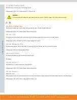
DANGER

During the anti-Legionella function the storage tank is heated up over the set value “Tmax S(X)”, which can lead to scalding 
and damage to the system.

CAUTION

This anti-Legionella function does not provide complete protection against Legionella, because the controller is dependent 
on suffi cient energy being fed in, and it is not possible to monitor the temperatures in the entire range of the storage tanks 
and the connected piping system. To provide complete protection against Legionella bacteria, it must be ensured that the 
temperature is raised to the necessary temperature, and at the same time there must be water circulation in the storage tank 
and piping system by means of other additional energy sources and external control units.

CAUTION

The anti-Legionella function is switched off at delivery.

Whenever heating-up has been carried out with the anti-Legionella function switched on, an information message with the 
date appears on the display.

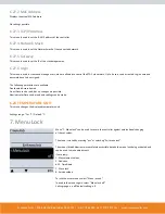
6.9 HEAT TRANSFER


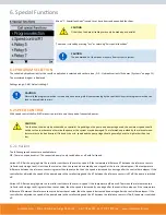
This is used to transfer energy from one storage to another with a pump.

Settings range: S1-S8, VFS1-2, Active storage/ Default setting: none

Temperature difference for heat transfer function.
When the temperature difference between HT Source and HT Drain reaches ΔT Heat Transfer On, the relay is switched on. As sson as the differ

-

ence drops to ΔT Heat Transfer Off, the relay is switched off again.

On: Settings range: 5-20 K/ Default setting: 8 K
Off: Settings range: 2 K to ΔT Ein / Default setting: 4 K

6.9.1 ΔT Heat Transfer

Setpoint temperature of the target storage
When this temperature is detected in the target storage, heat transfer is switched off.

Settings range: S1-S8, VFS1-2, Active storage/ Default setting: none

6.9.2 Setpoint

Содержание SmartMaxx-Pro-XL6D

Страница 1: ...INSTALLATION GUIDE SMARTMAXX SOLAR CONTROLLERS WWW SUNMAXXSOLAR COM MODEL NUMBER SmartMaxx DHWPlus SmartMaxx Pro XL6D X ...

Страница 2: ...ty Instructions 2 A Description of Controller 4 B Installation 5 C Terminal Connection 9 6 Table of Contents Operation 18 E Measurement Values 20 1 Statistics 20 2 Operating Modes 21 3 Settings 22 4 Protections 24 5 Special Functions 26 6 Menu Lock 45 7 Service Values 46 8 Languages 46 9 Malfunctions 46 Z ...

Страница 3: ...ance of the unit may only be carried out by specialists who possess the appropriate training For the user Make sure that the specialist gives you detailed information on the function and operation of the controller Always keep these instruc tions in the vicinity of the controller A 3 EXPLANATION OF SYMBOLS DANGER Failure to observe these instructions can result in danger to life from electric volt...

Страница 4: ...your solar or heating system The device is impres sive most of all for its functionality and simple almost self explanatory operation For each step in the input process the individual entry keys are assigned to appropriate functions and explained The controller menu contains headwords for the measured values and settings as well as help texts or clearly structured graphics The Pro XL6D can be used...

Страница 5: ...r AC1 AC3 Mechanical Relay R4 460VA for AC1 AC3 Mechanical Relay R5 460VA for AC1 AC3 Mechanical Relay R6 460VA for AC1 AC3 Mechanical Relay R7 460VA for AC1 AC3 0 10V Output for 10 k Ω working resistance PWM Output Freq 1 kHz level 10 V Internal Fuse 3x T2A 250V slow blow Protection Category IP40 Protection Class II Overvoltage Category II Degree of Pollution Category II Sensory Inputs 3x Pt1000 ...

Страница 6: ...allation CAUTION Install the controller only in dry areas and under the ambient conditions described under B 1 Specifications CAUTION Controller must be inac cessible from the rear 1 Unscrew cover screw completely 2 Remove Terminal connection cover Unscrew the 2 small screws left and right and remove the upper part of the controller by lifting it out of the socket 3 Mark the 3 mounting holes on th...

Страница 7: ...d by more than 55mm and the cable jacket must each into the housing just to the other side of the strain relief CAUTION Controller and VFS sensor have to have the same ground potential The VFS sensor has a functional earth connector PELV The PE connector of the controller has to be connected to the pipe system near the sensor CAUTION Low voltage cables such as temperature sensor cables must be rou...

Страница 8: ...Remove screw driver The clamp will lock the cable C 3 INSTALLING THE TEMPERATURE SENSORS The controller operates with Pt1000 temperature sensors which are accurate to the degree thus ensuring optimal control of system functions CAUTION The temperature sensor cables must be routed separately from mains voltage cables and must not for example be routed in the same cable duct CAUTION If desired the s...

Страница 9: ...n mode of the controller In Timer mode the temperature is controlled according to the set thermostat periods In Continous day mode the set periods are ignored and the temperature is controlled according to the Day time settings In Continous night mode the temperature is usually set to lowest This setting is best suited for periods of long absence like e g holidays Installation Carefully remove the...

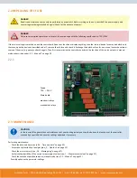
Страница 10: ...1 877 270 7875 fax www sunmaxxsolar com D 1 TERMINAL CONNECTION D Terminal Connection The mains part of the terminal connection room is covered by a plastic sheet Make sure that the controller is without voltage before removing it D 2 TERMINAL CONNECTION DIAGRAM ...

Страница 11: ...ble For R1 Optionally Selctable For R1 Optionally Selctable For R1 Optionally Selctable For R1 Optionally Selctable For R1 V2 Optionally Selctable For R2 Optionally Selctable For R2 Optionally Selctable For R2 Optionally Selctable For R2 R1 ELR Solar Pump Solar Pump Solar Pump Solar Pump Solar Pump Collector at S8 Solar Pump Collector at S8 Solar Pump R2 ELR Secondary Pump Secondary Pump Solar Pum...

Страница 12: ...y Selctable For R1 Optionally Selctable For R1 V2 Optionally Selctable For R2 Optionally Selctable For R2 Optionally Selctable For R2 Optionally Selctable For R2 R1 ELR Solar Pump Solar Pump Solar Pump Solar Pump Storage S1 Solar Pump Solar Pump Solar Pump R2 ELR Seconday Pump Secondary Pump Secondary Pump Secondary Pump R3 Valve Collector S7 Collector S8 On Col lector S7 Valve Storage S1 Storage ...

Страница 13: ...le For R2 Optionally Selctable For R2 Optionally Selctable For R2 Optionally Selctable For R2 Optionally Selctable For R2 R1 ELR Solar Pump Solar Pump Solar Pump Solar Pump Solar Pump Collector S8 Solar Pump Collector S8 Solar Pump Collector S8 R2 ELR Seconday Pump Seconday Pump Pool Seconday Pump Secondary Pump Solar pump2 Collector S7 Solar pump2 Collector S7 Secondary Pump R3 Valve Storage Top ...

Страница 14: ...Optionally Selctable For R2 Optionally Selctable For R2 Optionally Selctable For R2 R1 ELR Solar Pump Solar pump1 Collector S8 Solar Pump Pump Storage S1 Solar Pump Solar Pump Solar Pump R2 ELR Seconday Pump Pump Storage S2 Pump Storage S1 Secondary pump R3 Valve Collector On Charge Collector S7 Valve Collector On Charge Collector S7 Valve Storage S1 Storage S2 or S3 On Charge Storage S2 or S3 Pum...

Страница 15: ...R2 R1 ELR Solar Pump Solar pump Solar Pump Solar Pump Solar Pump Solar pump1 Collector an S8 Solar pump1 Collector an S8 R2 ELR Secondary pump Pool Pump Pool Pump Secondary pump in Storage circuit Secondary pump in Storage circuit Solar pump2 Collector an S7 Solar pump2 Collector an S7 R3 Valve Storage Top S1 On Open Valve Storage S1 and Storage S2 On Charge Storage S2 Valve Storage S1 On Open Val...

Страница 16: ...SunMaxx Solar 5098 NY 206 Bainbridge NY 13733 1 877 786 6299 1 877 270 7875 fax www sunmaxxsolar com ...

Страница 17: ...SunMaxx Solar 5098 NY 206 Bainbridge NY 13733 1 877 786 6299 1 877 270 7875 fax www sunmaxxsolar com ...

Страница 18: ...SunMaxx Solar 5098 NY 206 Bainbridge NY 13733 1 877 786 6299 1 877 270 7875 fax www sunmaxxsolar com ...

Страница 19: ...tion of fl ow in black Collector Storage Pool Temperature sensor Heat exchanger Load pause see Load time Warning error message New information available Logging is active More symbols can be found in the chapter Special functions E 2 COMMISSIONING HELP The fi rst time the controller is turned on and after the language and time are set a query appears as to whether you want to parametrise the contr...

Страница 20: ...NU STRUCTURE The graphics or overview mode appears when no key has been press for 2 minutes or when the main menu is exited by pressing esc The up and down buttons are used to scroll through the list of sensors and relays You can enter the Main menu by pressing the esc key The following menus are available 1 Measurements Current temperature values with explanations 2 Statistics Function control of...

Страница 21: ...nnected sensors and the specifi c device design 2 Statistics The menu 2 Statistics is used for function control and long term monitoring of the system The menu is closed by pressing esc or selecting Exit statistics CAUTION For analysis of the system data it is essential for the time to be set accurately on the controller Please note that the clock does not continue to run if the mains voltage is i...

Страница 22: ...ay and thus the connected consumer are switched on and off by pressing a key with no regard to the current temperatures and the param eters which have been set The measured temperatures are also shown to provide an overview and function control DANGER When operating mode Manual is activated the current temperatures and the selected parameters are no longer considered There is a danger of scalding ...

Страница 23: ...g 20 C 68 F 4 2 TMAX S X Switch off temperature at sensor X If this value is exceeded at the applicable sensor X the controller switches the associated pump and or valve off If the temperature falls below this value again and the other conditions are also met then the controller switches the pump and or valve on again Settings range 0 C to 99 C 32 F to 210 F Default setting 60 C 140 F DANGER Tempe...

Страница 24: ...her priority storage tank is exceeded Setting range from 0 C to 90 C 32 F to 194 F default setting 40 C 104 F 4 7 LOADING TIME Interruption of charging into the lower priority storage tank The charging of the lower priority storage tank is interrupted after the settable time in order to check whether the collector has reached a tempera ture level that allows charging in the higher priority storage...

Страница 25: ...ry high thus the pressure in the system will rise and can damage your system Pay close attention to the instructions of the system manufacturer 5 2 COLLECTOR PROTECTION Collector protection prevents overheating of the collector The pump is switched on to transfer heat from the collector to the storage tank If CP Ton is exceeded at the collector sensor the pump is switched on until the temperature ...

Страница 26: ...et value Frost stage 2 the controller switches the pump on continuously If the collector tem perature then exceeds the value Frost stage 2 by 2 C 36 F then the pump switches off again Frost protection setting range on off default setting off Frost stage 1 setting range from 25 C to 10 C 13 F to 50 F or off default setting 7 C 45 F Frost stage 2 setting range from 25 C to 8 C 13 F to 46 F must be l...

Страница 27: ... the min speed and the pump stage should generally be set to high rather than too low 6 2 1 Variant The following speed variants are available here Off There is no speed control The connected pump is only switched on or off with full speed Variant V1 After the purging time the controller switches to the set max speed If the temperature difference ΔT between the reference sensors collector and stor...

Страница 28: ... contains the settings for 0 10V or PWM pump CAUTION When selecting this submenu you may be prompted to save the speed control settings 6 2 3 1 Pump In this menu preconfi gured profi les for various pumps can be selected Please note that individual settings are still possible even when a profi le has been selected 6 2 3 2 Output Signal This menu determines the type of pump used Solar pumps perform...

Страница 29: ... voltage for the highest speed of the pump that is used e g during purging or manual operation Settings range Solar 5 0 to 10 0 V Default setting 10 0 V Heating 0 0 to 5 0 V Default setting 0 0 V 6 2 3 9 Speed When On This menu determines the calculated and displayed speed of the pump If e g 30 is set here and the signal set in PWM on 0 10V on is put out 30 speed is displayed When the signal set i...

Страница 30: ...age 27 chosen Purging time can not be applied with PWM or 0 10V output Settings range 5 to 600 seconds Default setting 8 seconds 6 2 5 Sweep Time Sweep time determines the inertia of the speed control to prevent strong fl uctuations in temperature Sweep time is the timespan for a complete change from minimum to maximum pump speed Settings range 1 to 15 minutes Default setting 4 minutes 6 2 6 Max S...

Страница 31: ... range 0 C to 90 C 32 F to 194 F Default setting 60 C 140 F RELAY FUNCTIONS RELAY FUNCTIONS The here explained additional functions can be assigned to unused relays Every additional function can only be used once Pay special attention to the technical data of the relays B 1 Specifi cations on page 5 6 3 SOLAR BYPASS Use the relay to switch a bypass valve or a bypass pump This can direct the fl ow ...

Страница 32: ...hermostat sensor 2 is exceeded Settings range S1 S8 VFS1 2 active storage Default setting none 6 4 4 Thermostat Sensor 2 Optional switch off sensor When T set hysteresis is exceeded at the optional thermostat sensor 2 the relay is switched off Settings range S1 S8 VFS1 2 active storage Default setting none 6 4 5 T eco For Energy saving mode When Energy saving mode is active During solar charge T e...

Страница 33: ... 99 C 32 F to 210 F Default setting 50 C 122 F 6 5 2 Co Hysteresis If the temperature at th drops below Co T set hysteresis the relay is switched off Settings range 50 bis 1 Default setting 10 6 5 3 Cooling Sensor Reference sensor of the cooling function Settings range Storage sensor Default setting First storage 6 5 4 Periods Cooling activity times Set the desired periods of time when the cooling...

Страница 34: ...tive Storage Default setting none 6 6 4 Storage Sensor Determines the storage sensor Settings range S1 S8 VFS1 2 active Storage Default setting none 6 7 COLLECTOR FIELD COOLING This function controls an external coolig unit to cool down the collector Settings range On Off If this temperature is exceeded at the reference sensor the relay is switched on Settings range 100 C to 180 C 212 F to 356 F D...

Страница 35: ...the time set in AL residence time at the AL sensors for a successful heat up Settings range 60 C to 99 C 140 F to 210 F Default setting 70 C 158 F 6 8 1 AL T Set This determines the time span for which the AL T set temperature must be detected for a successfull AL heat up Settings range 1 120 min Default setting 60 min 6 8 2 AL Residence Time This displays the date and time of the last successful ...

Страница 36: ...irculation in the storage tank and piping system by means of other additional energy sources and external control units CAUTION The anti Legionella function is switched off at delivery Whenever heating up has been carried out with the anti Legionella function switched on an information message with the date appears on the display 6 9 HEAT TRANSFER This is used to transfer energy from one storage t...

Страница 37: ... on difference When this temperature difference is reached the relay is switched on Settings range 5 20 K Default setting 8 K Switch off difference When this temperature difference is reached the relay is switched off Settings range 2 19 K Default setting 4 K the upper limit is the switch on difference 6 10 1 ΔT Difference Heat source sensor for Difference function This determines the sensor for t...

Страница 38: ...11 1 SF Tmax Minimum temperature in the solid fuel boiler to switch on the pump If the temperature at the boiler sensor is below this temperature the relay is disabled Settings range 0 C to 100 C 32 F to 212 F Default setting 70 C 158 F 6 11 2 SF Tmin Switch on and Switch off condition for the temperature difference between boiler and storage Switch on difference Δ T SF Settings range 5 to 20 K De...

Страница 39: ...SSURE MONITOR The relay is switched on when one or more protective funtion is active or a message is shown The relay is switched on when the pressure drops below set minimum or exceeds the set maximum pressure Settings range On Off Default setting Off Type of pressure sensor This menu is used to determine the type of pressure sensor used Please note If e g VFS1 is connected RPS1 option is not show...

Страница 40: ...s how long after the start of R1 or R2 the parallel relay is switched on Settings range 0 120 seconds Default setting 30 seconds 6 15 1 Delay This menu determines how long after the switch off of R1 or R2 the parallel relay is switched off Settings range 0 120 seconds Default setting 30 seconds 6 15 2 Followup Time 6 16 ALWAYS ON Relay is always switched on 6 17 HEATING CIRCUIT Heat circuit pump i...

Страница 41: ...he heat meter mode Flow rate is selected an approximated heat quantity is calculated using the values the user has to enter These are type of glycol AntiFreeze glycol portion and fl ow rate These values are put into correlation with the temperature data of collector sensor and storage sensor If necessary a correction value for ΔT can be set Since for the heat meter the collector and the storage te...

Страница 42: ...perature difference Since for the heat meter the collector and the storage temperature are used a difference to the fl ow respectively return flow temperature can be compensated by changing Offset ΔT accordingly Example Displayed collector temp 40 C 104 F measured flow temperature 39 C 102 F displayed storage temperature 30 C 86 F measured return temperature 31 C 88 F results in a correction value...

Страница 43: ...ngs range Off 0 0 6 bar 0 1 bar 0 1 6 bar 0 2 5 bar 0 4 bar 0 6 bar 0 10 bar Default setting Off 6 18 11 1 RPS1 RPS2 Minimum pressure If this value is undershot an error message is displayed and the relay is switched on Settings range Off 0 0 to 1 6 bar Default setting 6 18 11 2 Pmin Maximum pressure If this value is exceeded an error message is displayed and the relay is switched on Settings rang...

Страница 44: ...n made can be reset thus returning the controller to its delivery state CAUTION The entire parametrisation analyses etc of the controller will be lost irrevocably The controller must then be commissioned once again 6 22 SD CARD Settings for the data logging and fi rmware update function with SD card Activate the logging function and set the fi le format used Settings range CSV TSV JSON Off Default...

Страница 45: ...help setting range on off default setting off Purging time setting range 2 30 sec default setting 5 sec Increase setting range 1 C 10 C default setting 3 C min CAUTION This function should only be activated by a specialist if problems arise with acquisition of measurement values In particular follow the instructions from the collector manufacturer 6 24 TIME AND DATE This menu is used to set the cu...

Страница 46: ...rmissions are available Deactivated Access denied Guest Data can be read but no changes are possible Administrator Data can be read and settings can be made 6 27 6 Login 6 28 TEMPERATURE UNIT This menu changes the displayed temperature unit Settings range F or C Default C 7 Menu Lock Menu 7 Menu lock can be used to secure the controller against unintentional changing of the set values The menu is ...

Страница 47: ...is queried automatically during initial commissioning The choice of languages may differ however depending on the device design Z Malfunctions If the controller detects a malfunction the red light fl ashes and the warning symbol also appears in the display If the error is no longer present the warning symbol changes to an info symbol and the red light no longer fl ashes To obtain more detailed inf...

Страница 48: ...cessary System protection Collector temperature overshot the set temperature the solar pump was switched OFF to prevent damage due to excessive heat Collector protection Collector temperature overshot the set temperature the solar pump was switched ON to prevent damage to the collector due to excessive heat Recooling Excessive heat was radiated via the collector to protect the system Frost protect...

Страница 49: ...f the power supply and secure it against being switched on again Check for the absence of power DANGER Only use the supplied spare fuses or fuses of the same design with the following specifi cations T2A 250V Z 2 1 Fuses T2A 250V Main board electronic relays mechanical relays Z 3 MAINTENANCE CAUTION In the course of the general annual maintenance of your heating system you should also have the fun...

Страница 50: ...6 22 4 Save confi gura tion on page 42 In the event of uncertainty as to the control response or malfunctions the service values are a proven and successful method for remote diagnosis Save the service values see 8 Service values on page 44 at the time that the suspected malfunction occurs Send the service value table with a brief description of the error to the specialist or manufacturer In progr...

Страница 51: ...5098 NY 206 Bainbridge NY 13733 1 877 786 6299 1 888 270 7875 fax WWW SUNMAXXSOLAR COM Hydraulic Variant Set Commissioned On Commissioned By Notes ...

Отзывы: