Chapter 3
Service
3-23
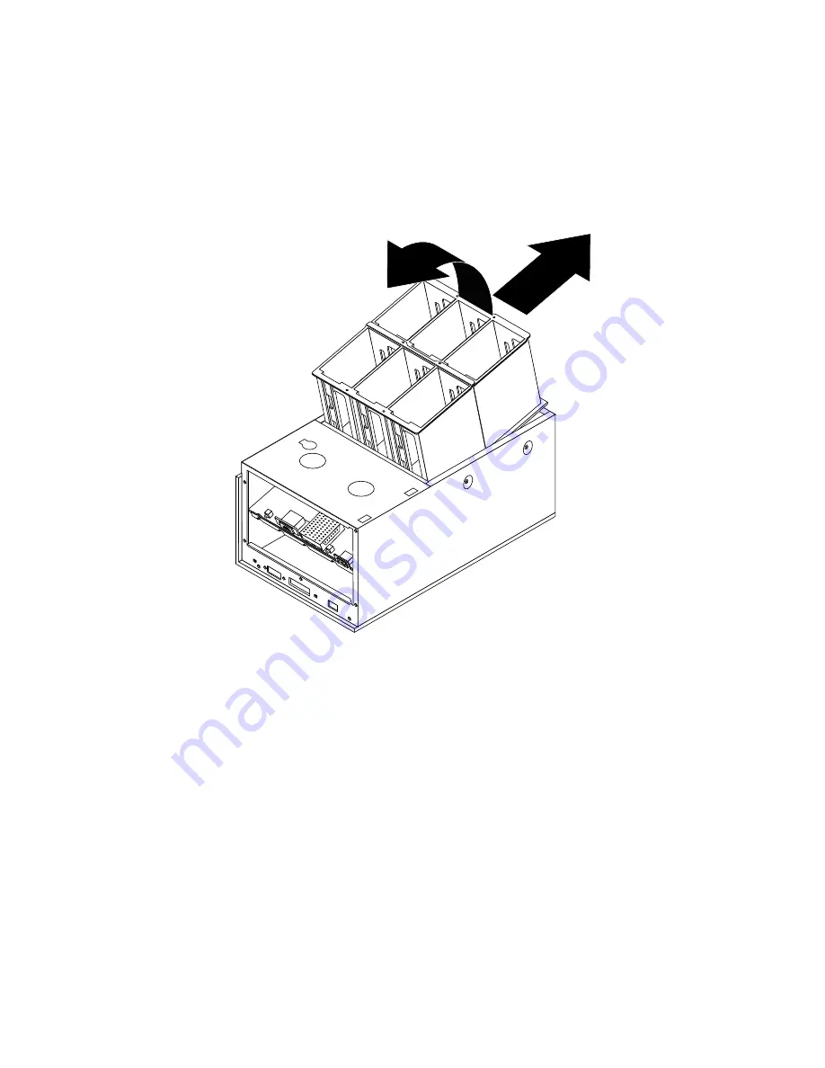
9. Pull the drive cage and backplane assembly upward until the assembly clears the
enclosure. Remove the assembly from the enclosure.
FIGURE 3-21
Removing the Drive Cage and Backplane Assembly
10. Reassemble the system.
a. Replace the drive cage and backplane assembly.
Slide the assembly towards the back of the system so that the screw holes align.
b. Replace the LED cable.
c. Replace the daughter board and the daughter board clip.
d. Replace the power supply.
e. Replace the drives.
f. Replace the drive access panel.
2
1
Содержание StorEdge MultiPack-FC
Страница 5: ...Regulatory Compliance Statements v...
Страница 6: ...vi Sun StorEdge MultiPack FC Installation Operation and Service Manual August 2000...
Страница 14: ...xiv Sun StorEdge MultiPack FC Installation Operation and Service Manual August 2000...
Страница 16: ...xvi Sun StorEdge MultiPack FC Installation Operation and Service Manual August 2000...
Страница 20: ...xx Sun StorEdge MultiPack FC Installation Operation and Service Manual August 2000...
Страница 24: ...xxiv Sun StorEdge MultiPack FC Installation Operation and Service Manual August 2000...
Страница 34: ...1 10 Sun StorEdge MultiPack FC Installation Operation and Service Manual August 2000...
Страница 50: ...2 16 Sun StorEdge MultiPack FC Installation Operation and Service Manual August 2000...
Страница 55: ...Chapter 3 Service 3 5 FIGURE 3 3 Removing the Power Supply FIGURE 3 4 Drive Cage With Backplane...
Страница 61: ...Chapter 3 Service 3 11 FIGURE 3 9 Opening the Drive Bracket FIGURE 3 10 Removing a Drive...
Страница 71: ...Chapter 3 Service 3 21 FIGURE 3 19 Drive Cage and Chassis Bottom Screws...
Страница 80: ...3 30 Sun StorEdge MultiPack FC Installation Operation and Service Manual August 2000...


