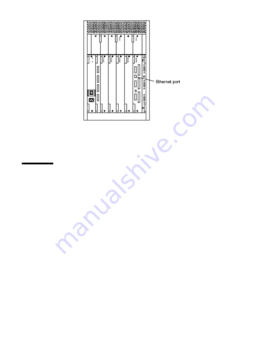
Sun Microsystems Enterprise 3500 Скачать руководство пользователя страница 27

Figure 2–5

10/100BASE-T Ethernet Connection

Connecting the System to the Network

1. Connect the network cable to a twisted-pair-to-transceiver interface box.

2. Connect the interface box with an appropriate cable to a network transceiver.

Figure 2–6 shows a typical arrangement for connecting the system to an Ethernet
network.

3. For Ethernet cables, determine if the cable has N-type screw-on connectors at

the ends.

Cabling the System

15

Содержание Enterprise 3500

Страница 1: ...Sun Enterprise 3500 System Installation Guide A Sun Microsystems Inc Business 901 San Antonio Road Palo Alto CA 94303 4900 Part No 805 2629 10 Revision A April 1998 ...

Страница 2: ...USA 650 960 1300 fax 650 969 9131 ...

Страница 3: ...Sun Enterprise 3500 System Installation Guide Part No 805 2629 10 Revision A April 1998 ...

Страница 4: ...PARTICULAR PURPOSE OR NON INFRINGEMENT Copyright 1998 Sun Microsystems Inc 901 San Antonio Road Palo Alto Californie 94303 4900 U S A Tous droits réservés Ce produit ou document est protégé par un copyright et distribué avec des licences qui en restreignent l utilisation la copie et la décompilation Aucune partie de ce produit ou de sa documentation associée ne peut être reproduite sous aucune for...

Страница 5: ...Using the User Naming Area 6 2 Cabling the System 9 Preparing the System for Cabling 9 Installing the Fiber Cable Organizer 9 Connecting the Power Cord 11 Connecting the Network Cable to the System 14 Connecting the System to the Network 15 Connecting an ASCII Terminal 18 Connecting the Fiber Cable to the I O Board 20 Connecting the Fiber Cable to the Interface Board and the I O Board 21 Wrapping ...

Страница 6: ...Software 35 Operating System Software and Patches 35 Solaris 2 6 Patch 105375 04 35 Solstice SyMON Software 35 Dynamic Reconfiguration 36 CPU Over Temperature Safeguard COS 36 A Regulatory Agency Compliance Statements 37 FCC DOC and VCCI Class Notices 37 FCC Class A Notice 37 DOC Class A Notice Avis DOC Classe A 38 VCCI 39 Declaration of Conformity 40 Index 41 v Sun Enterprise 3500 System Installa...

Страница 7: ... contain information on basic UNIX commands and procedures such as shutting down the system booting the system and configuring devices See one or more of the following for this information 4 Solaris 2 x Handbook for SMCC Peripherals which contains Solaris TM 2 x software commands 4 AnswerBook TM online documentation for the Solaris 2 x software environment 4 Other software documentation that you r...

Страница 8: ...ord AaBbCc123 Book titles new words or terms words to be emphasized Command line variable replace with a real name or value Read Chapter 6 in the User s Guide These are called class options You must be root to do this To delete a file type rm filename Shell Prompts TABLE P 2 Shell Prompts Shell Prompt C shell machine_name C shell superuser machine_name Bourne shell and Korn shell Bourne shell and ...

Страница 9: ...0 Sun Enterprise 6 5 4 3x00 Systems SIMM Installation Guide 802 5032 SBus and Graphics I O Boards 100 MB sec Fibre Channels for Sun Enterprise 6 5 4 3x00 Systems 805 2704 PCI I O Board Installation and Component Replacement for Sun Enterprise 6 5 4 3x00 Systems 805 1372 Sun Enterprise Peripheral Power Supply AC Installation Guide 802 5033 Sun Enterprise 3500 Auxiliary Peripheral Power Supply Insta...

Страница 10: ...01 30 81 61 92 Holland 06 022 34 45 06 022 34 46 Japan 0120 33 9096 0120 33 9097 Luxembourg 32 2 720 09 09 32 2 725 88 50 Sweden 020 79 57 26 020 79 57 27 Switzerland 0800 55 19 26 0800 55 19 27 United Kingdom 0800 89 88 88 0800 89 88 87 United States 1 800 873 7869 1 800 944 0661 World Wide Web http www sun com sunexpress Sun Documentation on the Web The docs sun com web site enables you to acces...

Страница 11: ...el can cause serious damage to this equipment Unqualified personnel who tamper with this equipment may be held liable for any resultant damage to the equipment Individuals who remove any outer panels or open covers to access this equipment must observe all safety precautions and ensure compliance with skill level requirements certification and all applicable local and national laws Procedures cont...

Страница 12: ...xi Sun Enterprise 3500 System Installation Guide Revision A April 1998 ...

Страница 13: ...installing the system are Unpacking the server Preparing the site Preparing the server Cabling Powering on Using the software Note For information about physical specifications electrical specifications and environmental requirements refer to Appendix A Specifications in the Sun Enterprise 3500 System Reference Manual part number 805 2630 1 ...

Страница 14: ...go to Preparing the Electrical Circuits on page 3 Caution The system can weigh up to 185 lbs 84 kg To prevent personal injury two people are needed to lift the system safely The rear support bracket is designed to support the system weight only when the system is stationary on a flat surface Do not attempt to lift the system by grasping the support bracket Tools 4 2 Phillips screwdriver 4 System k...

Страница 15: ...trical Circuits In planning where to place your equipment remember that each of the following items requires access by way of a separate power cord to a power outlet 4 Enterprise 3500 system 4 External peripherals 4 Monitor used for diagnostics The Enterprise 3500 system uses nominal input voltages of 100 120 VAC or 200 220 VAC Sun products are designed to work with single phase power systems havi...

Страница 16: ...s For twisted pair cable length see Table 2 1 A MII to AUI converter cable available from Sun enables the 10 100 Mbps Ethernet interface to run over 10 Mbps coaxial Ethernet networks Other MII Ethernet connectivity products are available from third parties Figure 1 2 and Figure 1 3 illustrate types of network cables and possible implementations of 10 100BASE T Ethernet Set up the network using Sun...

Страница 17: ...ions Sun equipment conforms to the Ethernet 10 100BASE T standard which states that the 10 100BASE T Link Integrity Test function should always be enabled on both the host and the hub If you have problems verifying connection between Sun equipment and your hub verify that your hub also has the link test function enabled Refer to Failure of Network Communications in the Sun Enterprise 3500 System R...

Страница 18: ...c or radio frequency interference Figure 1 4 Enterprise 3500 Server Access Areas Top View Using the User Naming Area To display the name of the server IP address owner or other important information on the front of the machine 1 Remove the front bezel Refer to Preparing for Service in the Sun Enterprise 3500 System Reference Manual see Front Bezel 2 Snap out the narrow transparent window From the ...

Страница 19: ... machine services 4 Use the colored paper provided with the system to make a label The available area for the paper label is 12 mm x 150 mm 0 5 in x 5 9 in Print or write the desired information in an area this size and cut the label to fit the transparent window 5 Place the paper label inside the window and snap the window back in place from the front side of the bezel Preparing for Installation ...

Страница 20: ...8 Sun Enterprise 3500 System Installation Guide Revision A April 1998 ...

Страница 21: ...ed in Chapter 1 Installing the Fiber Cable Organizer Use the fiber cable organizer to route the fiber optic cable to connect the interface board and the I O board A 2 meter cable is required when utilizing the internal FC AL disk drives The cable organizer can help prevent damage to the fiber optic cable by helping ensure the 1 0 inch minimum bend radius rule is observed The fiber cable organizer ...

Страница 22: ...izer clicks audibly into place 4 Install the left spool brace by repeating step 2 and step 3 5 Using the screw included in the kit fasten the spool braces to the support bracket through the center front cut out formed when both braces are in place 6 Remount the retainer clip through the hex nut at the notch on the side of the organizer Set the retainer clip screw into the hex nut 7 To wrap the 2 m...

Страница 23: ...e Power Cord 1 Use the key provided with your system to unlock and open the Enterprise 3500 system front door 2 Locate the system key switch in the upper right corner insert the key provided and turn the key switch to the Standby position See Figure 2 2 Cabling the System 11 ...

Страница 24: ...C just below the AC power switch Figure 2 3 5 Route the power cord through the power cord retainer clip In Step 6 on page 10 of Installing the Fiber Cable Organizer on page 9 you reattached the plastic clip to the cable organizer that you mounted on the rear support bracket Figure 2 3 a Use a Phillips screwdriver to open the plastic retainer clip Remove the screw b Place the power cord inside the ...

Страница 25: ... 220 240 VAC 15A circuit Figure 2 3 AC Power Switch AC Connector and Retainer Clip Caution Do NOT turn on power to the unit yet Doing so can cause system damage to occur See the next sections to connect the network cable to the system and to connect the system to the network Cabling the System 13 ...

Страница 26: ...e the network cable Figure 2 4 shows the twisted pair Ethernet network cable Figure 2 4 Network Cable 2 Connect one end of the network cable into the RJ 45 twisted pair network port For 10 100BASE T Ethernet the default interface port is the onboard connector on the I O board in slot 1 Figure 2 5 14 Sun Enterprise 3500 System Installation Guide Revision A April 1998 ...

Страница 27: ...wisted pair to transceiver interface box 2 Connect the interface box with an appropriate cable to a network transceiver Figure 2 6 shows a typical arrangement for connecting the system to an Ethernet network 3 For Ethernet cables determine if the cable has N type screw on connectors at the ends Cabling the System 15 ...

Страница 28: ...er connectors b Screw the other Ethernet coaxial cable into the other round screw on type connector on the transceiver 4 Determine if a terminator should be installed Table 2 1 lists the cabling limitations for Ethernet 5 If termination is required install a 50 ohm terminator in the unused transceiver N connector or at the end of the coaxial cable Use a female double N type connector Figure 2 6 sh...

Страница 29: ...10 Note 1 Finite lengths as constrained by transmission line phenomena Minimum length 23 4M maximum 500M If cable falls shorter than one of these values add cable to achieve next highest value 2 Transceivers are placed at intervals of 2 5 meters or multiples of 2 5 meters along the Ethernet cable Example transceivers are connected 2 5 meters apart not 2 0 meters Example transceivers are connected ...

Страница 30: ...Reference Manual part number 805 2630 and refer to the manual provided with your hub for more information about the Link Integrity Test function 6 If all cables are connected power on the system Connecting an ASCII Terminal An ASCII terminal or workstation can be attached to the server to display diagnostic messages produced by the firmware power on self test POST or OpenBoot TM PROM OBP program A...

Страница 31: ...he instruction manual shipped with the terminal for specific configuration instructions Note The setup parameters listed in Step 3 on page 19 may differ from the setup at the customer site These parameters can be changed in the NVRAM nonvolatile random access memory Refer to the set defaults and printenv commands in the OpenBoot Command Reference manual part number 802 3242 Cabling the System 19 ...

Страница 32: ...lled on the I O board Align the notch in the cable connector with the key notch in the module connector See Figure 2 9 4 Connect the other end of the fiber cable into the GBIC connector on the SPARCstorage TM Array or other storage device with fiber optic interface rear panel Align the notch in the cable connector with the notch in the connector on the storage device rear panel 20 Sun Enterprise 3...

Страница 33: ... Fiber Cable to the Interface Board and the I O Board Internal FC AL disk drives require an interface board IB to communicate via the I O board Figure 2 10 identifies the GBIC ports on the interface board and Table 2 2 identifies the GBIC associated with each disk drive Cabling the System 21 ...

Страница 34: ...4 5 6 7 B GBIC UB Upper bank Note Reserve disk bay 0 for the boot disk Wrapping the Fiber Cable on the Organizer To ensure that the fiber optic cable minimum bend radius rule 1 0 inch is observed use this procedure to wrap the cable around the spool organizer 1 Remove the two plastic caps that cover the cable connector on the GBIC module 22 Sun Enterprise 3500 System Installation Guide Revision A ...

Страница 35: ...e disk drive Align the notch in the cable connector with the key notch in the GBIC module connector See Figure 2 11 Figure 2 11 Fiber Cable Ports on the Interface Board 4 Route the fiber cable down toward the bottom of the system placing it through the left side restraints on the organizer 5 Wrap the cable around the fiber cable organizer spools mounted on the system rear support bracket in a figu...

Страница 36: ...ad the cable back through the center restraints then down and around the left spool Figure 2 12 Fiber Cable in Figure 8 Pattern 6 Repeat step 5 until the cable is the desired length finishing on the right side Thread the cable through the right side restraints and connect it to the I O board 24 Sun Enterprise 3500 System Installation Guide Revision A April 1998 ...

Страница 37: ...ential cables For differential SCSI cables the maximum is 25 meters When calculating the total length of a SCSI string include external cables internal cables and printed traces Table 2 3 lists internal measurements for the Enterprise servers TABLE 2 3 Internal SCSI Lengths Approximate Location Internal Length SBus I O board 0 43 meter Graphics I O board 0 43 meter For information on device addres...

Страница 38: ...oard SCSI 2 port or an SBus card installed in an appropriate SBus slot Figure 2 13 shows the location of the onboard single ended SCSI connector on the I O board Figure 2 13 Onboard Single ended SCSI Connector on the I O Board 2 Connect the other end of the SCSI cable to the external SCSI 2 device 3 Power on the system and test the server 26 Sun Enterprise 3500 System Installation Guide Revision A...

Страница 39: ...on for the first time Caution JumpStart may incorrectly install the system as a standalone workstation You should prevent JumpStart automatic installation from proceeding if the appropriate server specific configuration information is not in place Information about the JumpStart feature is on a card titled JumpStart Installation Instructions that is provided with the system documentation To preven...

Страница 40: ... door b Turn the system key switch to the Standby position See Figure 3 1 c Turn the AC power sequencer power switch to Off The AC power sequencer is at the rear of the enclosure See Figure 3 2 d Verify that the AC power cord is plugged into a wall socket Caution Do not disconnect the power cord from the wall socket when working on the server This connection provides a ground path that prevents da...

Страница 41: ...this LED turns off if the tests pass If the LED remains lit after 60 seconds a test has failed 4 The right front panel LED green flashes to show that boot is successful and the operating system is running If this LED fails to turn on and the middle LED is on a severe hardware fault exists Caution Never move the system when the power is on Failure to heed this warning may result in catastrophic dis...

Страница 42: ... firmware completes a successful reconfiguration in response to detected faults the system boots Note If faulty parts are detected and configured out of the working system you and the system manager must decide whether to operate the system until replacement parts arrive or to halt operation Also if a faulty component cannot be replaced in the field the entire subassembly like the system board mus...

Страница 43: ...actual message displayed on the screen will depend on the software running on your system 5 slot Sun Enterprise 3500 Keyboard Present OpenBoot FCS MB memory installed Serial Ethernet address Host ID If firmware indicates a hardware problem at this time refer to the Troubleshooting section in the Sun Enterprise 3500 System Reference Manual for further instructions Boot the system using the procedur...

Страница 44: ...m Status LED Note The system is in OBP if the left LED is on green the middle LED is flashing yellow and the right LED is off After the boot process completes check the status of the system by inspecting system status LEDs on the front panel See Figure 3 4 and Table 3 1 which summarize LED status indications 32 Sun Enterprise 3500 System Installation Guide Revision A April 1998 ...

Страница 45: ...tem is in OBP Ideally when the self test completes both left and right LEDs are on Less ideal is if all LEDs are on system needs service but is able to run The worst condition is if the left and middle LEDs are on system cannot boot or if no LED is on Powering Off the System Before turning off the system power you must halt the operating system See the Preface UNIX Commands to find references if y...

Страница 46: ...t door and pull on the handle to open the door 6 Locate the system key switch in the upper right corner and turn the key switch to the Standby position fully counterclockwise See Figure 3 1 7 Turn off the system power in this order 1 External drives and expansion cabinets if any 2 System AC power switch see Figure 3 2 3 Terminal For more system administration information on methods for shut down a...

Страница 47: ... with your system 4 Your Sun Enterprise system is configured with a Sun StorEdge TM A5000 device Contact your authorized Sun support provider about patch information for other Solaris operating environments Solstice SyMON Software Solstice TM SyMON TM features a graphical user interface GUI display that shows various graphs reflecting system status Solstice SyMON intended to complement network wid...

Страница 48: ...erver Check with your Sun sales representative or systems engineer for information on the availability of DR The online Dynamic Reconfiguration User s Guide for Sun Enterprise Systems provides information about preparing your server to use DR and instructions for performing DR operations CPU Over Temperature Safeguard COS The CPU over temperature safeguard COS software feature is automatically ava...

Страница 49: ... Union CE mark Europe Please read the appropriate section that corresponds to the marking on your Sun product before attempting to install the product FCC DOC and VCCI Class Notices FCC Class A Notice This device complies with Part 15 of the FCC Rules Operation is subject to the following two conditions 1 This device may not cause harmful interference 2 This device must accept any interference rec...

Страница 50: ...correct the interference at his own expense Shielded Cables Connections between the workstation and peripherals must be made using shielded cables in order to maintain compliance with FCC radio frequency emission limits Networking connections can be made using unshielded twisted pair UTP cables Modifications Any modifications made to this device that are not approved by Sun Microsystems TM Inc may...

Страница 51: ...VCCI Regulatory Agency Compliance Statements 39 ...

Страница 52: ...Declaration of Conformity 40 Sun Enterprise 3500 System Installation Guide Revision A April 1998 ...

Страница 53: ...Index Index 41 ...

Отзывы: