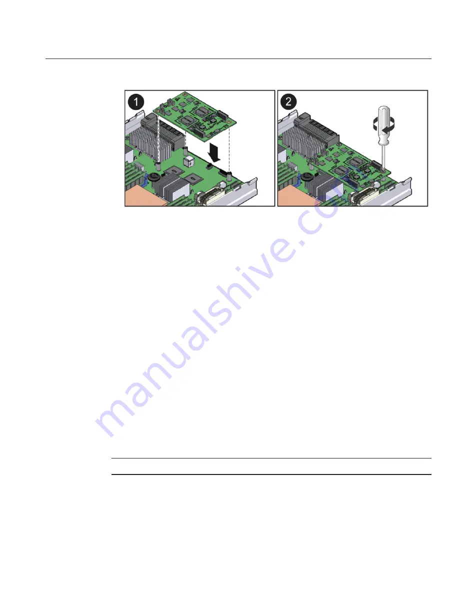
Position the SP board with the connector facing downward.
Align the underside connector on the SP board with the connector on the motherboard.
The three screw holes on the SP board line up with the standoffs on the motherboard when the
connectors are aligned.
Lower the SP board until the two connectors touch and carefully push down on the SP board
until the connectors engage one another.
Use a number 2 Phillips screwdriver to secure the SP board to the standoffs on the motherboard
using the three screws.
Prepare the server module for operation. See
“How to Prepare the Server Module for Operation”
on page 34
.
Update the system with the BIOS/ILOM firmware package you downloaded earlier (see the
“Before You Begin”information in
“How to Remove the Service Processor Board”on page 53
.
This will ensure that both the BIOS and ILOM firmware (which are packaged and tested
together) are at a supported level.
For information about updating firmware, see
Oracle Integrated Lights Out Manager (ILOM
) 3.0 Supplement for the Sun Blade X6275 M2 Server Module
.
Removing and Installing USB Flash Drives
Note –
This component is a customer-replaceable unit (CRU).
Two USB flash drive ports are located on the motherboard at the rear of the server module
underneath the SP board. The top USB port is for compute node 0. The bottom USB port is for
compute node 1. It is not necessary to remove the SP board to access the USB ports.
2
3
4
5
6
7
Removing and Installing USB Flash Drives
55
Содержание Blade X6275 M2
Страница 1: ...Sun Blade X6275 M2 Server Module Service Manual Part No 821 1084 March 2013...
Страница 6: ...6...
Страница 12: ...12...
Страница 18: ...18...
Страница 136: ...136...


