25
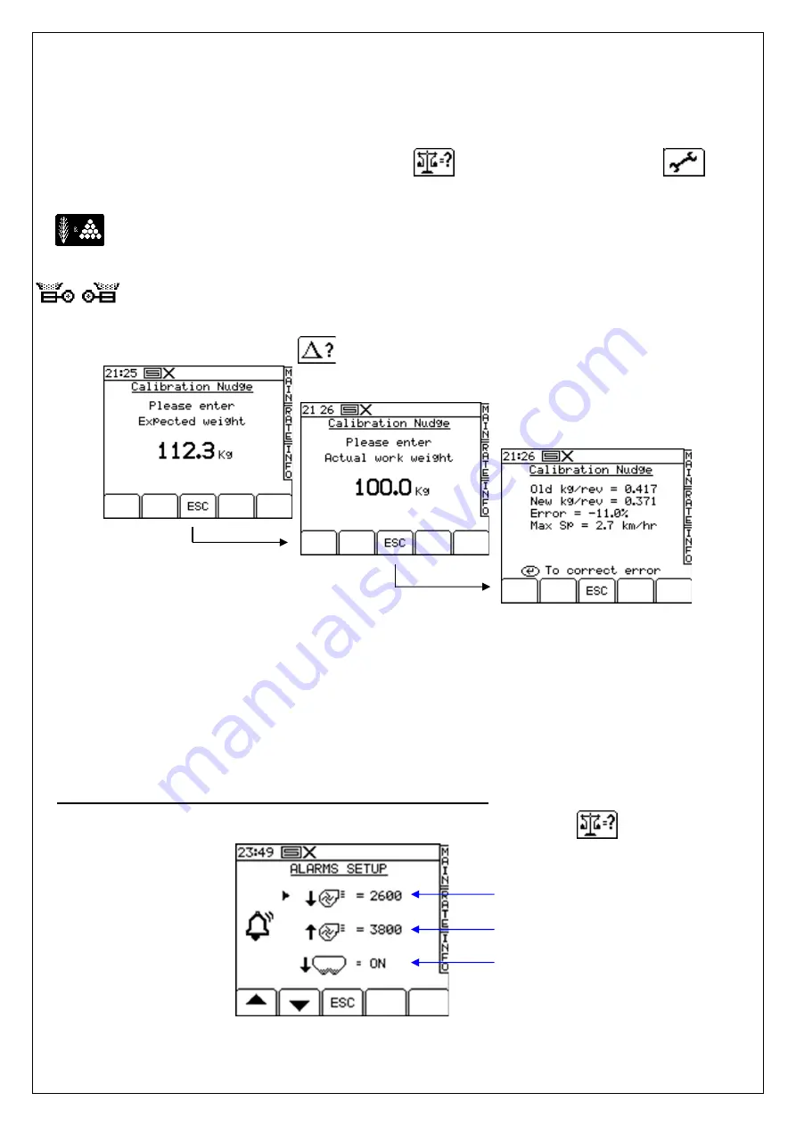
4.7.2 ‘CALIBRATION NUDGE’ - Adjusting the calibration factor
The ‘calibration nudge’ procedure enables you to adjust the existing calibration factor without
having to redo a bucket test.
1. First note down the PART TOTAL for the product displayed in the INFO screen. This is the
theoretical quantity that the instrument has calculated.
From the SETUP menu, press either the
key (CAL. CHECK), or the
key
(DRILL SETUP).
If the instrument is configured for dual products, first select the product you want to calibrate
(Fig.15).
If configured for dual metering units, likewise, first select the left or right unit (Fig.16)
2. From either screen, press the key to select the ‘Calibration Nudge’ screen (Fig.21).
3.
Enter the theoretical (‘Expected’) weight noted from the INFO screen at step 1 and press
ENTER twice.
4.
Enter the actual weight dispensed and press ENTER twice.
5.
The cal factor is re-calculated and displayed along with the % error and maximum forward
speed (Fig.23). Press ENTER again to store the new factor.
4.8 Set Fan Speed and Hopper Level alarm thresholds
To view the alarm thresholds (Fig. 24), from the SETUP menu, press the
key.
Figure 24. Alarm set up screen
To adjust the threshold, simply enter the figure and press the ENTER key.
Low fan speed
alarm
High fan speed
alarm
Hopper level alarm
(ON/OFF)
Figure 21. Calibration
nudge screen
Figure 22. Enter amount
screen
Figure 23. Nudge confirmation data
Содержание DTS 3m
Страница 46: ...46 9 5 Coulter system 9 6 Fan Motor system...
Страница 47: ...47 9 7 Wings Markers system...


