background image

Specifications


21


Regulatory Compliance 

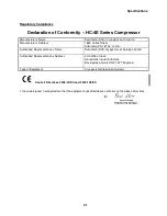
Declaration of Conformity – HC-4E Series Compressor 


Manufacturer’s Name 

Sumitomo (SCAI) Cryogenics of America 

Manufacturer’s Address 

1833 Vultee Street 
Allentown, PA 18103   U.S.A. 

Authorized Representative’s Name 

Sumitomo (SHI) Cryogenics of Europe Limited 
 

Authorized Representative’s Address 

3 Hamilton Close 
Houndmills Industrial Estate 
Basingstoke, Hants RG21 6YT England


Type of Equipment 

Cryogenic Refrigeration Systems 


Council Directives 2006/42/EC and 2004/108/EC 

 
I, the undersigned, hereby declare that the equipment specified above conforms to the above Directives. 


Содержание HC-4E1

Страница 1: ...HC 4E1 and HC 4E2 Helium Compressors Technical Manual Sumitomo SHI Cryogenics of America Inc 1833 Vultee Street Allentown PA 18103 4783 U S A Revision C August 2012 267318A...

Страница 2: ......

Страница 3: ...onmental Requirements 19 Protective Earth Terminal 19 Maintenance Intervals 19 Installation Kit 20 Adapter Fittings Optional Accessory 20 Remote On Off Cable Optional Accessory 20 Supplier Name and Ad...

Страница 4: ...9 Cables 60 ILLUSTRATIONS LIST Figure 1 HC 4E Flow Diagram 9 Figure 2 HC 4E1 Outline Dimensions and Parts Identification 14 Figure 3 HC 4E2 Outline Dimensions and Parts Identification 15 Figure 4 Conn...

Страница 5: ...his technical manual They appear as follows and serve the purposes stated WARNINGS call attention to actions or conditions that can result in serious injury or death to personnel CAUTIONS call attenti...

Страница 6: ...en disconnecting a gas line coupling to avoid loosening the cold head or compressor coupling Gas pressure can project the coupling with enough force to cause serious injury The compressor is charged w...

Страница 7: ...so trip Disconnect the power to the compressor Interchange any two incoming power leads except ground at the compressor s power cord plug or at the customer s disconnect switch Reconnect the power and...

Страница 8: ...4 This page is intentionally blank...

Страница 9: ...G21 6YT United Kingdom TEL 44 1256 853333 FAX 44 1256 471507 Sumitomo SHI Cryogenics of Europe GmbH Daimlerweg 5a D 64293 Darmstadt Germany TEL 49 6151 860 610 FAX 49 6151 800 252 Asia Sumitomo Heavy...

Страница 10: ...6 This page is intentionally blank...

Страница 11: ...f the closed cycle cryogenic refrigeration system The information in this manual pertains only to the HC 4E Series Compressors Other components used to form an operating system are described in separa...

Страница 12: ...8 This page is intentionally blank...

Страница 13: ...Supply Pressure Gauge 2 Oil Injection Orifice 12 Gas Equalization Solenoid Valve 3 Heat Exchanger 13 Gas Supply Coupling 4 Compressor Capsule 14 Gas Return Coupling 5 Oil Separator 15 Water Supply Fit...

Страница 14: ...the gas in three stages The first stage is by precipitation when the gas passes over the motor windings The second stage is in the oil separator whose element collects oil mist from the gas oil is agg...

Страница 15: ...cal power from the compressor to the cold head The compressor can be supplied with cables for operating a DE 202 DE 204SL M204S or CH204S Cold Head Compressor Capsule The rotary positive displacement...

Страница 16: ...d oil which continues to absorb heat from the compressor Internal Relief Valve The internal by pass valve opens to allow the compressor to be run when the system gas lines are disconnected to avoid ov...

Страница 17: ...temperature is too high The switch resets automatically after it cools Surge Bottle The surge bottle located in the return gas line dampens the pressure pulsations Water High Temperature Switch Locat...

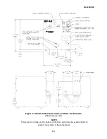
Страница 18: ...ription 14 Figure 2 HC 4E1 Outline Dimensions and Parts Identification Dimensions in mm NOTE Three 3 8 mm holes at the bottom of the front panel may be used for bolts to prevent movement of the compre...

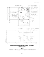
Страница 19: ...ription 15 Figure 3 HC 4E2 Outline Dimensions and Parts Identification Dimensions in mm NOTE Three 3 8 mm holes at the bottom of the front panel may be used for bolts to prevent movement of the compre...

Страница 20: ...16 This page is intentionally blank...

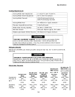
Страница 21: ...ed rotor current Power Cord Connector NEMA L6 20P 2 pole 3 wire 20 A 250 V male plug to connect to customer s receptacle Power Conductor Requirements for hard wiring if not using the compressor power...

Страница 22: ...damage the cooling system Refrigerant Quality Refrigerant is 99 995 pure helium gas with a dew point less than 50 C 58 F at 2070 kPa 300 psig PRESERVE YOUR WARRANTY and AVOID CONTAMINATION Specificat...

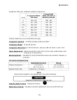
Страница 23: ...504 mm x 430 mm x 485 mm 19 8 x 16 9 x 19 1 Space Requirements Allow at least 600 mm 24 from the front back and both sides of the compressor for maintenance Mounting Position Compressor must be mount...

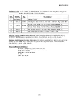
Страница 24: ...emale Brass 1 2 O D Tube Swagelok B 812 1 5 22908 1 Bag Polyethylene Clear 14 x 20 x 4 Mils Thick Adapter Fittings Optional Accessories Valved Swagelok Aeroquip fittings for charging venting or gas cl...

Страница 25: ...18103 U S A Authorized Representative s Name Sumitomo SHI Cryogenics of Europe Limited Authorized Representative s Address 3 Hamilton Close Houndmills Industrial Estate Basingstoke Hants RG21 6YT Engl...

Страница 26: ...22 This page is intentionally blank...

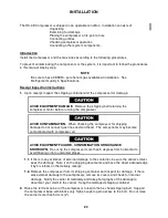
Страница 27: ...the compressor for shipping damage do not connect gas lines and cold head The components may become contaminated with compressor oil AVOID EQUIPMENT FAILURE CONTAMINATION OR NUISANCE SHUTDOWN Do not t...

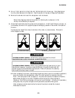
Страница 28: ...trical supply equipment must meet applicable codes and be installed by qualified personnel AVOID ELECTRIC SHOCK Permit only qualified electrical technicians to open electrical enclosures to perform el...

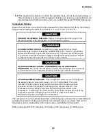
Страница 29: ...an result in serious injury or death AVOID EQUIPMENT FAILURE CONTAMINATION OR A NUISANCE SHUTDOWN Do not tip the compressor greater than 5 degrees from horizontal to avoid flowing oil into unwanted pl...

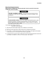
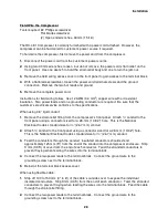
Страница 30: ...sts with the power supply connected and wiring exposed Failure to observe this warning can result in serious injury or death Tools required 2 Phillips screwdriver Flat blade torque screwdriver 1 Disco...

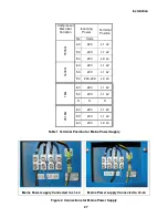
Страница 31: ...1 L2 50 220 L3 L4 1618G 60 220 L1 L2 50 200 L1 L2 50 230 240 L3 L4 18G 60 220 L1 L2 50 200 L1 L2 X X X 2518G 60 220 L1 L2 50 200 L1 L2 60 200 L3 L4 Table 1 Terminal Position for Mains Power Supply Mai...

Страница 32: ...uit 1 Remove the strain relief fitting from the compressor s front panel Attach conduit to the front panel using a connector sized for a 28 mm 1 3 32 hole This is the National Electrical Code s standa...

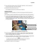
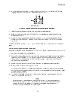
Страница 33: ...e customer s cooling water or coolant supply valve Turn on the coolant and check the lines for leaks Tighten the fittings if necessary See Specifications for cooling requirements Figure 5 Connect and...

Страница 34: ...line or due to a sharp bend near the connection NOTE Retain the threaded protective caps and plugs to re cover the couplings when they are not in use They protect the couplings from damage and prevent...

Страница 35: ...the compressor 2 Remove the heat shrink cap from one end of the remote on off cable Connect the cable to customer s remote switch Use the green conductor to ground the switch box Switch voltage will...

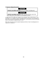
Страница 36: ...hipping bolt P N 70498 was installed on the compressor when it left the factory If the compressor is to be shipped reinstall the shipping bolt from the bottom of the compressor s base panel to restrai...

Страница 37: ...uctions on charging cleaning and leak checking Starting Close the circuit breaker by pushing up the handle Press the power switch The indicator in the switch will light The compressor will start Any i...

Страница 38: ...34 This page is intentionally blank...

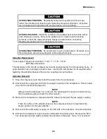
Страница 39: ...ure can cause serious injury if the system equipment ruptures AVOID INJURY FROM BURNS During operation some surfaces in the compressor capsule become hot Allow the compressor to cool for 1 2 hour afte...

Страница 40: ...0 000 operating hours A used adsorber has no salvage or repair value Venting the compressor is not required when replacing the adsorber because the gas line couplings are self sealing Adsorber Removal...

Страница 41: ...t through the front panel 3 Apply Loctite 242 to the threads of the bolt used to secure the adsorber to the base Install and tighten this bolt and lock washer Lower the elevated compressor to the floo...

Страница 42: ...fittings listed in step 4 1 Stop the compressor With two wrenches remove the gas line or the gas manifold assembly from the return gas Aeroquip coupling on the compressor 2 The adapter fitting is char...

Страница 43: ...e or the supply gas manifold assembly from the compressor 3 Be sure the valve on the adapter fitting is closed Using two wrenches attach it to the supply coupling on the compressor 4 Slowly open the v...

Страница 44: ...ompressor s interior has been opened to the atmosphere or the equalization pressure is 140 kPa 20 psig or lower Gas cleanup is performed with the compressor disconnected from the other system componen...

Страница 45: ...Open the valve on the adapter fitting and charge the compressor to the equalization pressure Close the charge valve on the adapter fitting Start the compressor 13 After running 30 to 45 seconds stop...

Страница 46: ...brazed and welded joints The flat gasket in the face of the Aeroquip male coupling seals the joint A leak at this gasket seal can be detected only when a gas line is connected A leak here can be caus...

Страница 47: ...AI Service Center Venting the adsorber will introduce contaminants to the system that cannot be removed in the field NOTE To repair a manifold assembly coupling vent the manifold to atmospheric pressu...

Страница 48: ...Maintenance 44 Figure 7 Compressor Shell High Temperature Switch Terminal Box Cover Temperature Overload Switch in Retainer...

Страница 49: ...ons The motor over current relay automatically resets after the compressor shuts down and the relay cools To restart the compressor press the power switch to the on position If the compressor fails to...

Страница 50: ...n for about one minute then goes off but the compressor does not start Defective motor control circuit Consult a SCAI Service Center Wrong voltage Compare the electric service with system specificatio...

Страница 51: ...sists Component failure in the power circuit Check for an open circuit breaker or fuse Reset or replace if necessary Check for a faulty component Incorrect current draw Measure the current Check motor...

Страница 52: ...ontinuity resistance and grounding will isolate most motor electrical problems Current measurements will separate a locked rotor condition from other electrical problems When the checks indicate a fau...

Страница 53: ...2 ohms If the resistance is outside this range consult a SCAI Service Center If there is no continuity the winding is open Consult a SCAI Service Center 6 With an ohmmeter check for continuity betwee...

Страница 54: ...compressor A reading of 0 amperes indicates an open circuit A reading of 10 to 14 amperes steady state is normal A reading slightly higher than 10 to 14 amperes suggests possible minor system problems...

Страница 55: ...Troubleshooting 51 Figure 9 HC 4E1 Wiring Diagram...

Страница 56: ...Troubleshooting 52 Figure 10 HC 4E2 Wiring Diagram...

Страница 57: ...Troubleshooting 53 Figure 11 HC 4E1 Electrical Schematic...

Страница 58: ...Troubleshooting 54 Figure 12 HC 4E2 Electrical Schematic...

Страница 59: ...ts Identification and Numbers See Figures 2 3 13 14 and 15 Item Part Name Part Number 1 Pressure gauge panel mount 2 dial 50987 2 Circuit breaker 20A 250 V 2 pole 38888 3 O ring 2 Aeroquip coupling 47...

Страница 60: ...38890 21 Compressor shell high temperature switch 256034A2P 22 Water high temperature switch 38862 23 Time delay relay replacement kit F37476A 24 Power cord assembly 267286B 25 Oil charging vessel wi...

Страница 61: ...Parts 57 Figure 13 Parts Identification 18 21 19 13 14 20 16...

Страница 62: ...Parts 58 Figure 14 Parts Identification for HC 4E1 Figure 15 Parts Identification for HC 4E2 15 23 27 23 17 15 17 28...

Страница 63: ...ies from SCAI Item Quantity Part Name Part Number Figure 1 2 Adapter fitting 8F 1 and 8M 2 with valve 266395C 16 2 2 Adapter fitting 8Fwith valve 255919B2 17 1 Denotes size 8 female Aeroquip coupling...

Страница 64: ...uantity Description Part Number 1 1 Accessory cable for remote On Off 6 m 20 ft long 263887B20 2 1 Cold head cable DE202 204SL 3 3 m 11 ft long 263941Bxxx 3 1 Cold head cable M204S 3 3 m 11 ft long 26...

Отзывы: