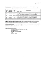
Description
12
Fuses:
#
Electrical Rating
(250 VAC)
Circuit
Location
HC-4E1
HC-4E2
FU1
0.63 AT
1.0 AT
Cold head
Front panel
FU2
0.63 AT
1.0 AT
Cold head
Front panel
FU3
5.0 AT
5.0 AT
Cold head
Front panel
FU4
5.0 AT
5.0 AT
Cold head
Front panel
FU5
0.4 AT
0.4 AT
Control
Inside Electrical Chassis
FU6
0.4 AT
0.4 AT
Control
Inside Electrical Chassis
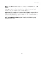
Gas Equalization Solenoid Valve:
This solenoid valve opens when the compressor is stopped.
The valve allows the helium gas pressure across the compressor to equalize, to prevent oil from
being blown out of the compressor into the low-pressure (return) gas line.
Gas High Temperature Switch:
Located on the supply gas line near the top of the
compressor,
the switch opens at 93
º
C (200
º
F) and stops the compressor if the gas temperature is too high.
Gas Supply and Return Couplings:
Both are self-sealing, size 8, male, Aeroquip, bulkhead
couplings and are the points of connection on the front panel for the rest of the system.
Heat Exchanger:
The heat exchanger consists of three coils wrapped around the compressor
capsule. One cools helium, another cools the compressor shell and another cools oil in the oil
injection circuit. This circuit cools oil that has absorbed heat from the compressor and reinjects
the cooled oil, which continues to absorb heat from the compressor.
Internal Relief Valve:
The internal by-pass valve opens to allow the compressor to be run when
the system gas lines are disconnected, to avoid overloading the compressor capsule.
Oil Capillary:
The capillary returns oil collected in the oil separator sump to the low-pressure
side of the compressor for recycling.
Oil Filters:
There are two oil filters. One filter in the oil separator drain line protects the return
oil capillary. The other filter in the oil injection circuit protects the compressor.
Oil High Temperature Switch:
Located on the oil return line, the switch opens at 60
º
C (140
º
F)
and stops the compressor if the oil temperature is too high.
Oil Injection Orifice:
This orifice is installed downstream of the oil filter in the oil injection line
and controls the flow rate of oil into the compressor’s gas return line.
Oil Separator:
The bottom of the oil separator serves as a sump. A cartridge above the sump
contains fibrous material that acts as the separating agent. Entrained oil coalesces on it,
forming large droplets that drain into the sump. This unit needs no servicing or replacement.
Power On/Off Switch:
This on/off rocker switch starts and stops the compressor. The switch
lights to indicate that power is on to the compressor.
Pressure Gauge:
A pressure gauge indicates gas pressure in the supply line. When the
compressor is not running, the gauge shows the equalization pressure.
Содержание HC-4E1
Страница 2: ......
Страница 8: ...4 This page is intentionally blank...
Страница 10: ...6 This page is intentionally blank...
Страница 12: ...8 This page is intentionally blank...
Страница 20: ...16 This page is intentionally blank...
Страница 26: ...22 This page is intentionally blank...
Страница 38: ...34 This page is intentionally blank...
Страница 55: ...Troubleshooting 51 Figure 9 HC 4E1 Wiring Diagram...
Страница 56: ...Troubleshooting 52 Figure 10 HC 4E2 Wiring Diagram...
Страница 57: ...Troubleshooting 53 Figure 11 HC 4E1 Electrical Schematic...
Страница 58: ...Troubleshooting 54 Figure 12 HC 4E2 Electrical Schematic...
Страница 61: ...Parts 57 Figure 13 Parts Identification 18 21 19 13 14 20 16...


