Section 2
DESCRIPTION
11
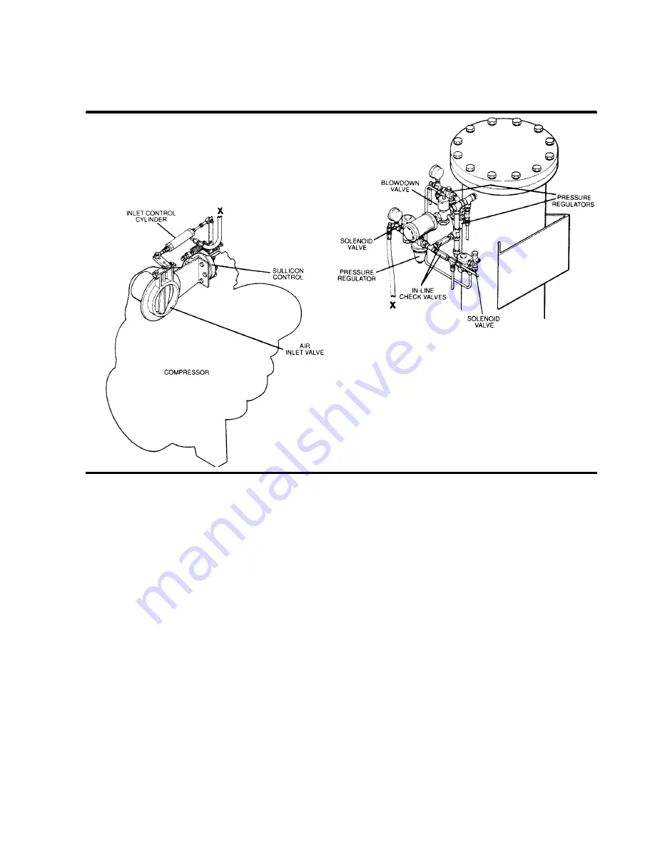
Figure 2-6 Control System
MODULATING MODE -- 340 TO 360 PSIG (2344
TO 2482kPa)
If less than the rated capacity of compressed air is
being used, the service line pressure will rise above
340 PSIG (2344kPa). The pilot pressure regulator
valve gradually opens, applying air pressure to the
Sullicon Control which partially closes the butterfly
valve on the compressor air inlet reducing the
amount of air entering the compressor until it
matches the amount of air being used. The Control
System functions continually in this manner, be-
tween the limits of 340 to 360 PSIG (2343 to
2481kPa), in response to varying demands from the
service line.
The pilot pressure regulator has an orifice which
vents a small amount of air to the atmosphere when
the pressure regulator controls the butterfly valve.
UNLOAD MODE -- IN EXCESS OF 360 PSIG
(2482kPa) LINE PRESSURE
When a relatively small amount, or no air is being
used, the service line pressure rises to the setting
(cut--out pressure) of the pressure switch. The pres-
sure switch opens, interrupting the electrical power
to the solenoid--type pilot valve. At this time, the pilot
valve allows dry sump tank air pressure to be ap-
plied directly to the Sullicon Control keeping the but-
terfly valve closed. Simultaneously, the pilot valve
sends a pneumatic signal to the blowdown valve.
The blowdown valve opens the sump to the atmo-
sphere, reducing the sump pressure to approxi-
mately 160 to 180 PSIG (1103 to 1241kPa).
The check valve in the air service line prevents the
pressure from returning to the sump.
When the line pressure drops back to the low setting
(cut--in pressure) of the pressure switch (usually
340 PSIG [2344kPa]), the pressure switch closes,
re--energizing the three--way pilot valve and allow-
ing the blowdown valve to close. The re--energized
pilot valve again prevents line pressure from reach-
ing the Sullicon Control. Should the pressure begin
to rise, the pilot pressure regulator will resume its
normal function as previously described.
For a compressor with varied periods of time when
there are not air requirements, a “Dual Control” op-
tion is available. This option allows you to set the
compressor in an automatic position whereby the
compressor will shut down (time delayed) when no
compressed air requirement is present and restart
as compressed air is needed.
Содержание 20/12 500 CFM
Страница 12: ...Section 2 DESCRIPTION 8 Figure 2 3 Piping and Instrumentation...
Страница 14: ...Section 2 DESCRIPTION 10 Figure 2 5 Capacity Control System Typical...
Страница 18: ...14 NOTES...
Страница 20: ...16 NOTES...
Страница 24: ...20 NOTES...
Страница 38: ...34 NOTES...
Страница 40: ...Section 7 ILLUSTRATIONS AND PARTS LIST 36 7 3 MOTOR FRAME COMPRESSOR AND PARTS...
Страница 42: ...Section 7 ILLUSTRATIONS AND PARTS LIST 38 7 4 AIR INLET SYSTEM...
Страница 44: ...Section 7 ILLUSTRATIONS AND PARTS LIST 40 7 5 COOLING AND LUBRICATION SYSTEM...
Страница 46: ...Section 7 ILLUSTRATIONS AND PARTS LIST 42 7 6 COOLER ASSEMBLY...
Страница 48: ...Section 7 ILLUSTRATIONS AND PARTS LIST 44 7 7 DISCHARGE SYSTEM...
Страница 50: ...Section 7 ILLUSTRATIONS AND PARTS LIST 46 7 7 DISCHARGE SYSTEM...
Страница 52: ...Section 7 ILLUSTRATIONS AND PARTS LIST 48 7 8 INSTRUMENT PANEL AND PARTS...
Страница 54: ...Section 7 ILLUSTRATIONS AND PARTS LIST 50 7 9 CONTROL SYSTEM...
Страница 56: ...Section 7 ILLUSTRATIONS AND PARTS LIST 52 7 9 CONTROL SYSTEM...
Страница 58: ...Section 7 ILLUSTRATIONS AND PARTS LIST 54 7 10 ELECTRIC CONTROL BOX...
Страница 60: ...Section 7 ILLUSTRATIONS AND PARTS LIST 56 7 11 UNIT TUBING...
Страница 62: ...Section 7 ILLUSTRATIONS AND PARTS LIST 58 7 11 UNIT TUBING...
Страница 64: ...Section 7 ILLUSTRATIONS AND PARTS LIST 60 7 12 DECAL GROUP...


