Section 6
MAINTENANCE
30
* Repair Kit P/N 042246
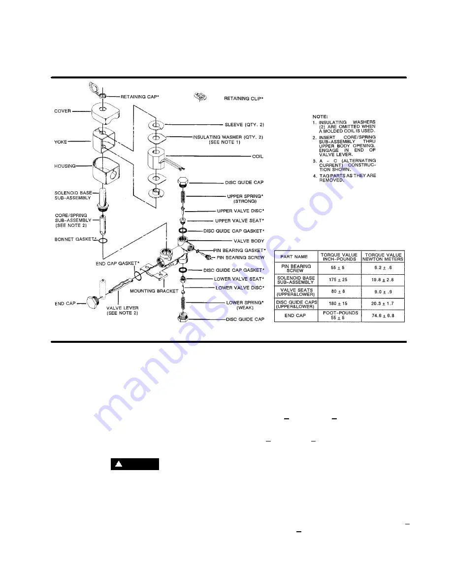
Figure 6-13 Pilot Valve (P/N 407390)
5. Remove end cap, end cap gasket and slip core/
spring assembly (A--C Construction) or core (D--C
Construction) off the end of the valve lever and lift
it out through solenoid base sub--assembly open-
ing.
6. Inspect upper and lower valve seats but
DO NOT
remove from valve body unless installing a com-
plete Spare Parts Kit.
7. Clean all parts thoroughly and replace worn or
damaged parts with a complete Spare Parts kit. If
a Spare Parts kit is required, refer to the section
on Installation of New Spare Parts Kit for com-
plete rebuild.
CAUTION
!
Install all new parts. DO NOT retain any old parts
when rebuilding valve. If only partial installation is
made,valve malfunction may occur.
VALVE ASSEMBLY
1. Reassemble in reverse order of disassembly pay-
ing careful attention to exploded view provided for
identification and placement of parts.
2. Lubricate all gaskets with Dow Corning’s Valve
Seal silicone lubricant or equivalent high grade sil-
icone grease.
3. Replace
core/spring
sub--assembly
(A--C
Construction or core (D--C Construction) through
solenoid base sub--assembly opening and en-
gage with lever.
4. Install end cap gasket and end cap. Torque end
cap to 55 + 5 ft./lbs. (75 + 7Nm).
5. Replace bonnet gasket and solenoid base sub--
assembly. Torque solenoid base sub--assembly to
175 + in./lbs. (20 + 3 Nm).
6. Replace solenoid enclosure and retaining cap or
clip.
7. Install valve discs. If lapping is required, refer to
the Lapping Seats and Discs section.
8. For stroke setting requirements (adjustment of
valve discs), refer to the New Seat and Disc Instal-
lation paragraphs of New Spare Parts Kit Section.
9. Install upper and lower springs. Refer to the New
Spring Installation section.
10. Replace disc guide cap gaskets and disc guide
caps (both ends). Torque disc guide caps to 180 +
15 in./lbs (20 + 2 Nm).
Содержание 20/12 500 CFM
Страница 12: ...Section 2 DESCRIPTION 8 Figure 2 3 Piping and Instrumentation...
Страница 14: ...Section 2 DESCRIPTION 10 Figure 2 5 Capacity Control System Typical...
Страница 18: ...14 NOTES...
Страница 20: ...16 NOTES...
Страница 24: ...20 NOTES...
Страница 38: ...34 NOTES...
Страница 40: ...Section 7 ILLUSTRATIONS AND PARTS LIST 36 7 3 MOTOR FRAME COMPRESSOR AND PARTS...
Страница 42: ...Section 7 ILLUSTRATIONS AND PARTS LIST 38 7 4 AIR INLET SYSTEM...
Страница 44: ...Section 7 ILLUSTRATIONS AND PARTS LIST 40 7 5 COOLING AND LUBRICATION SYSTEM...
Страница 46: ...Section 7 ILLUSTRATIONS AND PARTS LIST 42 7 6 COOLER ASSEMBLY...
Страница 48: ...Section 7 ILLUSTRATIONS AND PARTS LIST 44 7 7 DISCHARGE SYSTEM...
Страница 50: ...Section 7 ILLUSTRATIONS AND PARTS LIST 46 7 7 DISCHARGE SYSTEM...
Страница 52: ...Section 7 ILLUSTRATIONS AND PARTS LIST 48 7 8 INSTRUMENT PANEL AND PARTS...
Страница 54: ...Section 7 ILLUSTRATIONS AND PARTS LIST 50 7 9 CONTROL SYSTEM...
Страница 56: ...Section 7 ILLUSTRATIONS AND PARTS LIST 52 7 9 CONTROL SYSTEM...
Страница 58: ...Section 7 ILLUSTRATIONS AND PARTS LIST 54 7 10 ELECTRIC CONTROL BOX...
Страница 60: ...Section 7 ILLUSTRATIONS AND PARTS LIST 56 7 11 UNIT TUBING...
Страница 62: ...Section 7 ILLUSTRATIONS AND PARTS LIST 58 7 11 UNIT TUBING...
Страница 64: ...Section 7 ILLUSTRATIONS AND PARTS LIST 60 7 12 DECAL GROUP...


