Page 78
Component Access/Removal
Integrated (
Integrated (
700-
700-
2) Series
2) Series
7-11
#
3756780
- Revision D - July, 2005
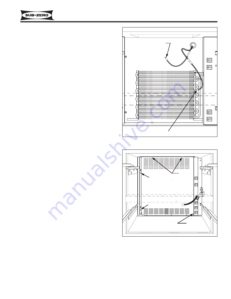
Lower Compartment Thermistor Removal
(700TR-2 Only)
NOTE:
The lower compartment thermistor in the
700TC/I-2 is attached inside the switch enclosure which
is explained later in this section.
The lower compartment thermistor in the model 700TR-
2 is located behind the evaporator cover, and is
attached to the back wall with a screw.
To access and remove the lower compartment thermis-
tor, first remove the two drawers, the heat exchanger
cover and the lower evaporator cover assembly. Then,
disconnect the thermistor wire leads from the wire har-
ness, and extract the screw which secures the thermis-
tor to the rear wall.
Lower Evaporator Thermistor Removal
(700TR-2 Only)
NOTE:
The lower evaporator thermistor in the 700TC/I-
2, 700TF/I-2 and 700TFI-2V is attached to the top right
side of the evaporator which is explained later in this
section.
The lower evaporator thermistor in the 700TR-2 is
attached to the right evaporator bracket with a screw.
To access and remove the lower evaporator thermistor,
first remove the two drawers, the heat exchanger cover
and the lower evaporator cover assembly. Then, dis-
connect the thermistor electrical leads and extract the
screw securing the thermistor to the right evaporator
bracket.
Lower Evaporator Cover Assembly Removal
(700TC/I-2, 700TF/I-2, 700TF/I-2V)
The lower evaporator cover in the 700TC/I-2, 700TF/I-2
and 700TF/I-2V is held in place with four screws and
one peg. Two screws on the left side are hidden by the
heat-exchanger cover; two screws at the top secure
the evaporator cover to the ceiling of the lower compart-
ment; and a peg protruding from the bottom left side of
the switch enclosure fits into a hole in the bottom right
side of the evaporator cover.
To access and remove the lower evaporator cover, first
remove the two drawers and the heat exchanger cover,
as well as the icemaker in applicable models. Then,
remove the two screws that were hidden by the heat
exchanger cover. Extract the two screws at the top and
pull the evaporator cover to the left to disengage the
peg from the hole at the bottom right. Now, pull the
assembly through the upper drawer opening.
Figure 7-26.
Evap Cover Removal, TC/I-2, TF/I-2 & TF/I-2V
Evaporator Cover
Screw
Screws
Screw
Peg
(Not Shown)
Figure 7-25. Lower Thermistors, TR-2
Evaporator Thermistor
Compartment Thermistor


