


-
4
-
© STULZ GmbH, Hamburg
-
4
-
INDEX
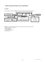
1 MODELS AND DESCRIPTION OF THE COMPONENTS ...................................................................... 6
1.1
Models .......................................................................................................................................... 6
1.2
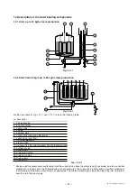
Description of the components ..................................................................................................... 7
1.3
Description of the water bearing components ............................................................................... 8
2 CONTROL- AND OPERATING PRINCIPLE ........................................................................................... 9
2.1 Operating principle ........................................................................................................................ 9
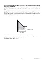
2.2 Control principles .......................................................................................................................... 9
3 MOUNTING ........................................................................................................................................ 12
3.1
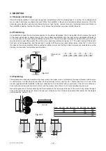
Receipt and storage .................................................................................................................... 12
3.2
Positioning ................................................................................................................................... 12
3.3
Fastening ..................................................................................................................................... 12
3.4
Removal and reassembly of the front cover ................................................................................ 13
4 WATER CONNECTIONS ...................................................................................................................... 14
4.1 Characteristics of the supply water ............................................................................................. 14
4.2
Characteristics of the drain water ................................................................................................ 15
4.3
Pipe connections ......................................................................................................................... 15
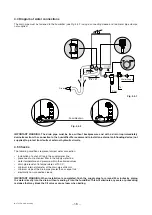
4.4
Diagram of water connections ..................................................................................................... 16
4.5
Checks ........................................................................................................................................ 16
5 STEAM DISTRIBUTION ........................................................................................................................ 17
5.1 Direct steam distribution: ventilated steam distributors ............................................................... 17
5.2
Steam distribution in cold rooms ................................................................................................. 17
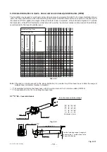
5.3
Steam distribution in ducts - linear and concentrated jet distributors (OEM) .............................. 18
5.4
Concentrated jet steam distributor (OEM) ................................................................................... 19
5.5
Positioning the linear distributors in the air duct .......................................................................... 19
5.6
Installation of the steam pipe ...................................................................................................... 20
5.7
Installation of the condensate return pipe ................................................................................... 21
5.8
Checks ........................................................................................................................................ 21
6 ELECTRICAL CONNECTIONS ............................................................................................................. 22
6.1
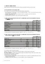
Power supply voltage .................................................................................................................. 22
6.2
Checking the voltage of the auxiliary circuit transformer ............................................................. 23
6.3
Main control board ...................................................................................................................... 23
6.4
External control signals ............................................................................................................... 25
6.5
Auxiliary contacts ........................................................................................................................ 27
6.6
Checks ........................................................................................................................................ 28
6.7
Single-phase wiring diagram for 1-5 kg/h humidifiers ................................................................. 29
6.8
Three-phase wiring diagram for 3-15 kg/h humidifiers ................................................................ 30
6.9
Three-phase wiring diagram for 25-65 kg/h humidifiers .............................................................. 31
6.10 Three-phase 25-65 kg/h boiler configuration............................................................................... 32
7 START-UP, CONTROL AND SHUT-DOWN ........................................................................................... 32
7.1 Preliminary checks ....................................................................................................................... 32
7.2 Starting the unit ............................................................................................................................ 33
7.3 The humidifier controller ............................................................................................................... 34
7.4 Shut-down .................................................................................................................................... 36


