


26
EN/02.2018/G17F © STULZ GmbH – all rights reserved
cyberlab original instructions
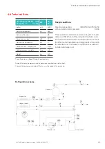
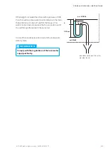
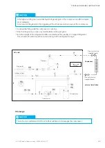
The reheat is connected in accordance with the electric diagram. It
is controlled and monitored by the controller. The values for switch-
ing on and off are adjusted in the „operate/components/heating“
menu on the controller. Refer to the operating instructions C7000.
The hotgas reheat is integrated in the refrigerant circuit in accord-
ance with the refrigerant diagram in the appendix. The refrigerant
supply is controlled via an electrically-actuated 3-way solenoid
valve. The solenoid valve is controlled via the controller. The con-
trol parameters are adjusted in the „operate/components/heating“
menu on the controller. Refer to the operating instructions C7000.
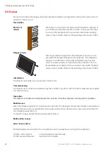
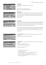
electrical
reheat
Hotgas reheat
Description
Installation
The reheats are installed and connected in the A/C unit.
Commissioning
The reheats are controlled and monitored by the controller of your A/C unit. No further measures are required
for commissioning.
Operation
The reheat is controlled and monitored by the controller. No further measures are required for operation.
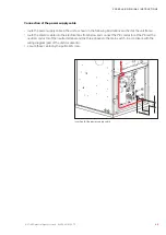
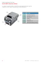
Maintenance
Clean the reheat annually from contaminations and check it for damage. The electrical reheat is located above
the electrical box and is accessible after opening the unit front door. Remove six screws and pull out the elec-
trical reheat towards the front.
To clean the hotgas reheat the rear wall must be removed.
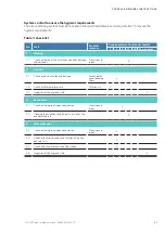
Malfunction causes
Alarm: Reheat defect
All reheat alarms are received by the controller and can be requested according to the equipment.
C7000-control system:
no display (display only externally)
C7000 advanced terminal:
indication on the display
5.5 Reheat
An electrical reheat and a hotgas reheat are installed complete and integrated in the function and method of
operation of the A/C unit.