


61
Grease Seal Installation Instructions
Centrifugal Pump Application
When replacing the seal, never mix old and new parts. Wear patterns on the old seal faces cannot be realigned during reassembly,
and use of old parts can result in premature failure of the new seal.
Before installing the seal, inspect the bore of the seal liner for
excessive wear or grooves that might cause leakage or damage
to the seal packing rings. If the seal liner must be replaced, use
the new seal liner and arbor (or hydraulic) press to force the
old one out. After the liner is installed, drill a ¼” diameter hole
through it to permit the flow of lubricant to the seal liner.
Be Careful to center the drill in the threaded lubrication hole
so not to damage the threads. Debur the hole from the
inside of the seal liner after drilling.
Clean the seal cavity and shaft with a cloth soaked in fresh
cleaning solvent. Be sure to follow all safety precautions described
on the solvent container.
Remove the new seal and inspect the precision finished faces to
ensure that they are free of any foreign matter. To ease installation of the
seal, lubricate the packing rings, spacer sleeve, and seal liner with water or a very small amount of oil
and apply a drop of light lubrication oil on the precision finished faces. Refer to the illustration, and
assemble the seal as follows.
Installation of the inboard rotating element is dictated by the configuration of the shaft shoulder. If there is a radius at the
shaft shoulder, the larger chamfer on the I.D. of the inboard rotating element must be positioned toward the shaft shoulder. If
there is an undercut at the shaft shoulder, the larger chamfer must be positioned away from the shaft shoulder. Determine
the correct position for the rotating element and slide it onto the shaft.
Sub assemble the inboard stationary element, packing ring and spring washer, and press this subassembly into the lubricated
seal liner. A push tube cut from a length of plastic will aid seal installation. The O.D. of the tube should be about the same
size as the O.D. of the seal spring.
Install the spacer sleeve and spring.
Sub assemble the outboard stationary element, packing ring and spring washer. Press this subassembly into the lubricated
seal liner. If the outboard rotating element has a chamfered side, install it with the chamfer facing the impeller end of the
shaft.
If your pump requires a spacer washer, install the spacer washer with the chamfer on the I.D. positioned toward the seal.
Install the impeller adjusting shims and impeller (consult the operator’s manual for impeller clearance and installation
instructions).
Before starting the pump, reinstall the automatic lubricating grease cup and piping (if removed for seal liner replacement).
Lubricate the seal as indicated below.
LUBRICATION
Fill the grease cup through the grease fitting with No. 2 lithium base grease until grease escapes from the relief hole. Turn the
grease cup arm counterclockwise until it is at the top of the stem; this will release the spring to apply grease to the seal.
NOTE:
Some smoking and leakage may occur after installing a
new seal assembly. This should stop after the pump has
run a while and the lapped seal faces have seated in.
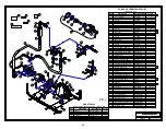
IMPELLER
SEAL PLATE
SPACER SLEEVE
SPRING
STATIONARY
WASHER
STATIONARY
WASHER
BRASS SEAL LINER
LARGE CHAMFER
PACKING RINGS
ENGINE
CRANKSHAFT
STATIONARY
ELEMENTS
ROTATING
ELEMENTS
IMPELLER
SHIM
WASHERS
Figure 3. Grease Seal Assembly
POSITION
FOR
FILLING
POSITION
WHEN
IN USE
POSITION
WHEN
EMPTY
Figure 4. Automatic Lubricating Grease Cup
GREASE
FITTING
CROSS
ARM
RELIEF
HOLE
Содержание M2-H
Страница 2: ...2 This page left blank intentionally ...
Страница 13: ...13 ...
Страница 18: ...18 M2 H Identifying Your Machine Components Location of Tags and PIN Plates ...
Страница 19: ...19 SECTION II Description Care and Maintenance ...
Страница 31: ...31 SECTION III Set up and Installation of Unit in Detail ...
Страница 33: ...33 SECTION IV Operating the M2 Unit ...
Страница 41: ...41 SECTION V Troubleshooting the M2 Unit ...
Страница 44: ...44 SECTION VI Periodic Maintenance Repair Information ...
Страница 49: ...49 SECTION VII OEM Repair Information ...
Страница 62: ...62 ...
Страница 63: ...63 ...
Страница 64: ...64 ...
Страница 68: ...68 SECTION VIII Parts Manual ...