


37
M2-H
Operating the M2 Unit
Typical Transfer/Offloading Operation
Transferring Operation
On the bottom of the filter / shear housing of the M2 you will see a second 1-1/2 in. ball valve
(1-1/2”NPT.) marked “Outlet”(the first “outlet” is connected to the internal tank jets)
A transfer hose with a minimum size of 1-1/2 in. can be attached to the ball valve to carry the finished
product to a holding tank or directly to the drill rig.
Make the necessary connections at the holding tank or the drill rig.
Run the M2 pump at a favorable speed and slowly rotate the ball valve handle to the open position, to
allow the fluid to flow to the holding tank or the drill rig.
The speed and pressure of the fluid flow is determined by the hydraulic motor speed.
If the unit is supplying the drilling rig directly, a valve that is controlled by the operator of the drill rig
will be needed to stop the flow (normally mounted on the drill rig). The tank jet valve will need to be in
the open position to act as a “relief” when the valve on the drill rig is closed.
If transferring to a reservoir tank, the “outlet” valve on the filter/shear housing is used to start / stop the
flow of fluid.
When removing the mixed fluid from the tank (to the drill rig or reservoir), leave an amount of fluid in
the bottom of the tank to keep the pump from sucking air (cavitation).
Close this “Outlet” valve, add water to the tank and begin mixing a new batch of mixed fluid.
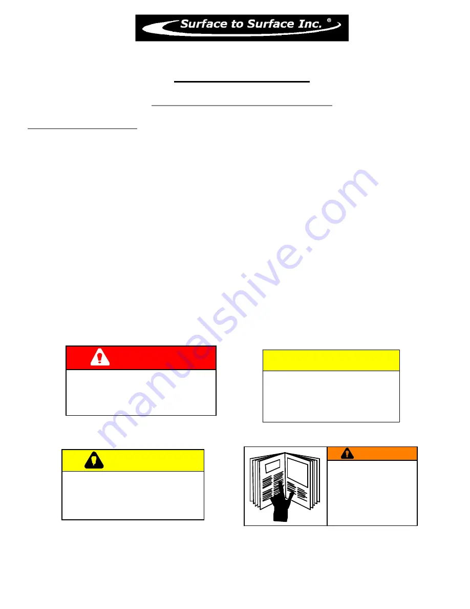
CAUTION
WHEN TRANSFERRING FLUID
to the drill rig, fluid pressure may
reach or exceed 50 p.s.i.
CHECK the drill rig manufacturers
specifications regarding maximum inlet
pressures allowed for their pump.
DANGER
IN AN EMERGENCY
rotate the flow control valve
lever to the STOP position
to halt the pump, and fluid flow.
CAUTION
WHEN THE UNIT
IS IN OPERATION,
the fluid in the piping may reach
pressures up to 50 p.s.i.
WARNING
REFER TO THE SAFETY
STATEMENTS IN THE
OEM SUPPLI ED MANUALS
AND
THIS MANUAL
REGARDI NG THESE
OPERATIONS.
Содержание M2-H
Страница 2: ...2 This page left blank intentionally ...
Страница 13: ...13 ...
Страница 18: ...18 M2 H Identifying Your Machine Components Location of Tags and PIN Plates ...
Страница 19: ...19 SECTION II Description Care and Maintenance ...
Страница 31: ...31 SECTION III Set up and Installation of Unit in Detail ...
Страница 33: ...33 SECTION IV Operating the M2 Unit ...
Страница 41: ...41 SECTION V Troubleshooting the M2 Unit ...
Страница 44: ...44 SECTION VI Periodic Maintenance Repair Information ...
Страница 49: ...49 SECTION VII OEM Repair Information ...
Страница 62: ...62 ...
Страница 63: ...63 ...
Страница 64: ...64 ...
Страница 68: ...68 SECTION VIII Parts Manual ...