background image

January, 1994

While Digital believes the information included in this publication is correct as of the date of

publication, it is subject to change without notice.

Digital Equipment Corporation makes no representations that the interconnection of its products

in the manner described in this document will not infringe existing or future patent rights, nor

do the descriptions contained in this document imply the granting of licenses to make, use, or sell

equipment or software in accordance with the description.

Any changes or modifications made to this equipment may void the user’s authority to operate the

equipment.

NOTE:

This equipment generates, uses, and may emit radio frequency energy. The equipment has

been type tested and found to comply with the limits for a Class A digital device pursuant to Part

15 of the FCC rules. These limits are designed to provide reasonable protection against harmful

interference in a residential installation.

Operation of this equipment in a residential area may cause interference in which case the user,

at his own expense, will be required to take whatever measures may be required to correct the

interference.

WARNING

This is a Class A product. In a domestic environment, this product may cause radio interference in

which case the user may be required to take adequate measures.

© Digital Equipment Corporation 1992, 1993, 1994.

Printed in the United States of America.

All rights reserved.

AXP, CI, DECchip, DEC 7000, DEC 10000, Digital, DSA, DSDF, HSD05, MSCP, OpenVMS, RF,

RA82, RF72, StorageWorks, TF, TMSCP, VAX, VAXcluster, VAX 4000, VAX 6000, and the DIGITAL

logo are trademarks of Digital Equipment Corporation.

Exabyte is a registered trademark of Exabyte Corporation.

All other trademarks and registered trademarks are the property of their respective holders.

The postpaid Reader’s Comments forms at the end of this document request your critical evaluation

to help prepare future documentation.

This document was prepared using VAX DOCUMENT Version 2.1.

Содержание HSD05

Страница 1: ...entation set It describes the HSD05 Array Controller and contains installation and configuration information For day to day operation this manual includes a description of the user interface commands...

Страница 2: ...against harmful interference in a residential installation Operation of this equipment in a residential area may cause interference in which case the user at his own expense will be required to take w...

Страница 3: ...itches and Jumpers 2 2 2 4 Setting the Device Configuration on the HSD05 Array Controller 2 4 2 4 1 DSSI ID 2 4 2 4 2 SCSI ID 2 6 2 4 3 Selecting Bus Termination 2 7 2 5 Installing the HSD05 Array Con...

Страница 4: ...3 18 3 4 1 Type 1 Error Logs for a Disk Drive 3 19 3 4 2 Type 1 Error Logs for a Tape Drive 3 20 3 4 3 Type 2 Error Logs for a Disk Drive 3 21 3 4 4 Type 2 Error Logs for a Tape Drive 3 22 3 5 Removin...

Страница 5: ...A 5 Tables 1 StorageWorks Related Documentation vii 1 1 HSD05 Array Controller and SBB Shelf Dimensions 1 5 1 2 Environmental Specifications 1 6 2 1 Thermal Stabilization Specifications 2 2 2 2 HSD05...

Страница 6: ......

Страница 7: ...eshoot the HSD05 array controller and a remove and replace procedure Appendix A Contains configuration information for the HSD05 and associated SBB shelves including a listing of cables This informati...

Страница 8: ...Boldface type indicates the first instance of terms being defined in text In code examples user input is shown in boldface type italic type Italic type indicates emphasis and complete manual titles O...

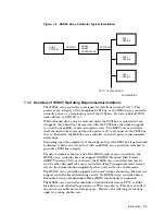
Страница 9: ...seven SCSI devices A DSSI bus connects to the HSD05 through a connector on the front panel SCSI bus connection is made through the shelf backplane connector The HSD05 is a TMSCP MSCP compliant device...

Страница 10: ...device served by the HSD05 array controller is independently addressable Attached disk tape and solid state drives appear to the host as standard DIGITAL storage architecture DSA devices Disk allocat...

Страница 11: ...onnected cold swap Depending upon the complexity of the configuration total DSSI bus length should be limited to between 30 to 60 feet with an HSD05 array controller attached to guarantee DSSI bus int...

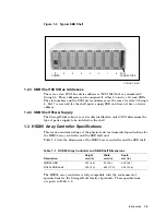
Страница 12: ...D05 array controller is fully compatible with the power and environmental requirements of StorageWorks family devices In a typical application the HSD05 array controller can be installed in an SBB she...

Страница 13: ...ution unit CDU determines the type of power supply to be installed in the shelf 1 3 HSD05 Array Controller Specifications This section contains listings of the physical and environmental specification...

Страница 14: ...et per minute Maximum Operating Environment Range Temperature 10 to 40 C 50 to 104 F Derate 1 8 C for each 1000 merters 1 0 F for each 1000 feet of altitude Maximum temperature gradient 11 C hr 20 F h...

Страница 15: ...rmally stabilize the HSD05 array controller and other SBBs based on the ambient shipping temperature CAUTION Be sure to thermally stabilize the HSD05 array controller in the operating environment prio...

Страница 16: ...vices or your local Digital sales office 2 Be sure to thermally stabilize the HSD05 array controller as given in Environmental Stabilization and Table 2 1 3 After removing the HSD05 array controller f...

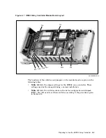
Страница 17: ...in the following tables Table 2 2 lists the jumper settings for the HSD05 array controller These settings need not be changed during a normal installation Table 2 3 lists the switch sections in the d...

Страница 18: ...ators installed 2 4 Setting the Device Configuration on the HSD05 Array Controller This section contains the procedure to set the switches on the HSD05 array controller module board prior to installat...

Страница 19: ...y on the bus and DSSI ID 0 has the lowest priority The DSSI ID is factory set to 0 you may need to change this ID to one that is currently not being used on your system Setting the DSSI ID Table 2 4 l...

Страница 20: ...l reach through the slot in the rear panel of the HSD05 array controller and set the switchpack to the DSSI ID number selected in Step 2 2 4 2 SCSI ID The SCSI port J2 plugs into the SBB shelf backpla...

Страница 21: ...e HSD05 array controller typically occupies one end of the DSSI bus this terminator is normally installed Make sure that the other end of the DSSI bus is properly terminated Note The DSSI bus uses two...

Страница 22: ...SBB slot and on cable configuration rules for the SBB shelf Installation Procedure Use the following procedure to install the HSD05 array controller in the SBB shelf 1 Remove power from the shelf by r...

Страница 23: ...ws 1 Connect the input power cable s to the power supply SBB s in the shelf 2 Verify that the Shelf Status indicator on the power supply SBB is lit If this indicator is not lit refer to the StorageWor...

Страница 24: ...operation of the subsystem In the following sections user input is shown in boldface type in the examples 2 7 1 Starting PARAMS from the Console Prompt on OpenVMS VAX Systems Use the following procedu...

Страница 25: ...Console Prompt on OpenVMS AXP Systems Use the following procedure to start PARAMS from the console prompt on OpenVMS AXP systems 1 At the console prompt enter the SHOW CONFIG command as shown in the...

Страница 26: ...AMS configuration utility display shows the settings for HSD05 array controller parameters At the PARAMS prompt enter SHOW ALL to display the current HSD05 parameters When entering this command a spac...

Страница 27: ...pecified as the value to be used in the thousands position of the MSCP unit ID such as x for DIAx210 This offset is automatically created by the system The unit offset values must be unique for each D...

Страница 28: ...n enabled the HSD05 array controller reports the RF72 device type The device type reported to the host does not affect the accessible disk space The factory default for this parameter is 1 enabled IMM...

Страница 29: ...lly described in The NAME_ALGRM Parameter SCSI_ID_X Used in conjunction with the NAME_ALGRM parameter to set alternative device names for each SCSI ID The NAME_ALGRM Parameter The NAME_ALGRM parameter...

Страница 30: ...he SHOW and ALL qualifier The default settings are as follows PARAMS SHOW ALL Parameter Name Active Min Max Units NODENAME xxxxxx 1 8 Ascii SYSTEMID xxxxxx 1 268435456 DecimalNum DISK_ALCS 0 0 255 Dec...

Страница 31: ...tive Min Max Units NODENAME HSD1 1 8 Ascii SYSTEMID 131072 1 268435456 DecimalNum DISK_ALCS 10 0 255 DecimalNum TAPE_ALCS 0 0 255 DecimalNum INTERVAL 60 0 32768 Seconds SCSI_ID_4 40 0 9999 DecimalNum...

Страница 32: ...CE_TYPE to 0 These device types as reported to the host do not affect actual accessible device storage space Due to device geometry differences a disk drive served by the HSD05 array controller cannot...

Страница 33: ...ing system The onboard utilities are accessed through the diagnostic and utility protocol DUP server either through the system console or from the OpenVMS prompt In this chapter user input is shown in...

Страница 34: ...sh a connection to the HSD05 array controller SET HOST DUP DSSI a Starting DUP server Copyright C 1994 Digital HSD05 Serial No 8 Firmware Rev B1 X36 DIRECT V1 0 D Dec 21 1993 16 59 31 PARAMS V1 0 D De...

Страница 35: ...ID 6 ID 7 A SCSI P RZ73 Host B SCSI P RZ73 Host C DSSI P RF73 RF72 Host D DSSI P RF73 Host E SCSI P TZ85 RRD42 Host Futurebus P FBD0 Host System Status Pass Type b to boot duc1 1 0 2 0 This display is...

Страница 36: ...0 On OpenVMS AXP systems connect to the DUP server as follows MC SYSMAN IO CONNECT DUP_server NOADAPTER DRIVER SYS FDRIVER where DUP_server is the system DUP server and is typically FYA0 2 Enter the f...

Страница 37: ...devices by specifying the ALL qualifier as shown in Example 3 2 Example 3 2 SHOW Command Display UTILIT SHOW DIA220 Device SID Vendor Model Rev Dev Stat Maint Oper Maint Status DIA220 2 0 DEC RZ28 435...

Страница 38: ...l for example DIA100 Sequential access devices such as tape drives are specified with the MUA prefix for example MUA120 Example 3 3 is an example of the SELECT operation display Example 3 3 SELECT Ope...

Страница 39: ...TAPETEST operations These operations normally run until stopped with the ABORT command or by powering off the HSD05 array controller Command Syntax The following is the syntax of the ABORT command ABO...

Страница 40: ...ses with the QUALIFY command Once started you cannot abort the FORMAT operation Example 3 6 shows of a FORMAT operation display Example 3 6 FORMAT Operation Display UTILIT FORMAT DIA100 Device SID Ven...

Страница 41: ...You are prompted to confirm the qualify operation on the selected device Answering N or NO aborts the operation with no change to the data on the device Answering Y or YES to this prompt starts the q...

Страница 42: ...perform a write read disktest to write data to the disk before you perform the read only disktest You are prompted to confirm the DISKTEST operation on the selected drive Answering N or NO aborts the...

Страница 43: ...uding a filemark Block sizes start at 32 kilobytes and are halved on each successive write rewind read pass The test is restarted when the block size reaches 1 kilobyte You are prompted to confirm the...

Страница 44: ...r the SHOW command with the device_name qualifier to determine device status 2 If the device status is not AVAILABLE enter the appropriate operating system commands to make the device available to the...

Страница 45: ...IT SHOW DIA220 Device SID Vendor Model Rev Dev Stat Maint Oper Maint Status DIA220 2 0 DEC RZ28 435E AVAILABLE FORMAT READY UTILIT SHOW DIA220 Device SID Vendor Model Rev Dev Stat Maint Oper Maint Sta...

Страница 46: ...e DISKTEST command and specify the device_name of the device to be exercised 6 At the verification prompt check that the device name given under the Device header of the DISKTEST display is the device...

Страница 47: ...vice while troubleshooting the system TAPETEST Task Procedure Use the following procedure to exercise a specified tape device 1 At the UTILIT prompt enter the SHOW command with the device_name qualifi...

Страница 48: ...tiating Tape Test UTILIT SHOW MUA210 Device SID Vendor Model Rev Dev Stat Maint Oper Maint Status MUA210 1 0 DEC TLZ06 0491 MAINT TAPETEST PASS 0 UTILIT ABORT MUA210 UTILIT DESELECT MUA210 UTILIT 3 3...

Страница 49: ...by the number of times the indicator blinks The first digit of the code is separated from the second digit by a one second pause A two second pause separates the error code from its next repetition Th...

Страница 50: ...types of error logs there are also separate formats for disk and tape devices The following two tables contain information to be used in interpreting HSD05 array controller errors during OpenVMS error...

Страница 51: ...out Table 3 3 SCSI Bus Phases Code Phase 00 Data out 01 Data in 02 Command 03 Status 04 Reserved 05 Reserved 06 Message out 07 Message in 3 4 1 Type 1 Error Logs for a Disk Drive The following example...

Страница 52: ...he 01 in byte 7 indicates that the error occurred in the Data In phase 3 4 2 Type 1 Error Logs for a Tape Drive A type 1 error log for a tape drive reports information on a SCSI port problem in a form...

Страница 53: ...h a SCSI command problem LONGWORD1 00007002 LONGWORD2 00000006 LONGWORD3 00002900 LONGWORD4 00280000 LONGWORD5 98D01D00 To decipher the error log break up each longword into its constituent bytes as s...

Страница 54: ...12 and 13 of the Request Sense data 11 through 13 Bytes 15 through 17 of the Request Sense data 14 through 19 First six bytes of the SCSI command The following is an example of a type 2 error log for...

Страница 55: ...power be removed prior to replacement Failure to remove power can result in blowing one or more fuses in the devices on the DSSI bus Use the following procedure to remove and replace the HSD05 array...

Страница 56: ...ack CXO 4020A MC DSSI NODE ID NOT USED OPEN CLOSED SCSI ID SCSI TERMINATION 11 Perform the procedures in Sections 2 6 and 2 7 to configure and verify proper operation of the HSD05 array controller 3 2...

Страница 57: ...to connect an HSD05 array controller to DEC 4000 AXP Model 600 Distributed Departmental Servers VAX 4000 Systems and Servers A micro ribbon cable with 6 1 8 BC29R 06 One 50 pin right angle micro ribb...

Страница 58: ...shelf is mounted in the vertical position A micro ribbon cable with 3 0 98 BC29T 03 Two right angle connectors 9 3 0 BC29T 09 Use the following cable to connect the HSD05 trilink connectors when Both...

Страница 59: ...elf connection of the HSD05 and related SBB devices The diagrams are as follows Figure A 2 is a diagram of two interconnected SBB shelves Figure A 3 shows the DSSI bus terminated at the HSD05 array co...

Страница 60: ...ECTOR DSSI CABLE TO HOST OR ADJACENT DSSI NODE CONNECTION TO DSSI TERMINATOR OR ADJACENT DSSI NODE Figure A 3 DSSI Bus Terminated At The HSD05 Array Controller DSSI TERMINATOR ATTACHES TO TRILINK CONN...

Страница 61: ...d Point of DSSI Bus HSD05 WITH TRILINK CONNECTOR DSSI PORT WITH DSSI TERMINATION DSSI BUS HOST CXO 4055A MC DSSI NODE DSSI NODE DSSI NODE CABLE TYPE USE BC29S BC29T BC29U DSSI TERMINATOR HSD05 Configu...

Страница 62: ......

Страница 63: ...to 2 12 E Environmental specifications 1 5 Environmental stabilization 2 1 Error log 3 18 H HSD05 device fault 2 9 dimensions 1 5 DSSI connector 1 4 environment 1 5 indicators 1 4 install procedure 2...

Страница 64: ...ironmental 1 5 environmental stabilization 2 1 StorageWorks building block vii overview 1 4 related documents vii Switches DSSI ID 1 4 SCSI ID 1 4 T TAPETEST description 3 11 task 3 15 Task exercise d...

Отзывы: