background image

- 4 -

Table of Contents

Lift Jockey™

EXPLODED DIAGRAM AND PARTS LIST .................................................................. 39-83

Tilt Cylinder & Front Cowl  Assembly........................................................................... 40-41
Engine Cowl Assembly................................................................................................... 42-43
Engine Assembly ............................................................................................................ 44-45
Pump Assembly .............................................................................................................. 46-47
Battery/Hose Clamp Assembly ....................................................................................... 48-49
Steering Housing Assembly ............................................................................................ 50-51
Hydraulic Tank Assembly ............................................................................................... 52-53
Steering Handle/Fuel Tank  Assembly ............................................................................ 54-55
Platform/Brake Pedal Assembly ..................................................................................... 56-57
Brake Linkage Assembly ................................................................................................ 58-59
Wheel Motor, Brake & Tire Assembly ........................................................................... 60-61
Quick Change Hub Assembly......................................................................................... 62-63
Hand and Foot Mast Control Assembly ......................................................................... 64-65
Mast Assembly ............................................................................................................... 66-69
Lift Frame Assembly ...................................................................................................... 70-71
Hydraulic Piping Schematic ........................................................................................... 72-75
Hydraulic System Schematic .......................................................................................... 76-77
Electrical Wiring Schematic ........................................................................................... 78-79
Decal Identification/Location ......................................................................................... 80-83

CALIFORNIA PROPOSITION 65 WARNING.............................................................. IBC

Содержание Lift Jockey LJS2000

Страница 1: ...SERVICE PARTS MANUAL MODEL LJS2000 REVISION B 6 2003 PN 56590 Lift Jockey Narrow A 100 employee owned American manufacturer...

Страница 2: ......

Страница 3: ...20 Know Your Lift 20 Fluids and Lubrication 21 Fuel Tank 22 Hydraulic Oil 22 Hydraulic Oil Filter 23 Hydraulic Breather Cap 23 Lubrication Points 24 Engine 25 Cooling System Valve Clearance Battery Po...

Страница 4: ...ank Assembly 52 53 Steering Handle Fuel Tank Assembly 54 55 Platform Brake Pedal Assembly 56 57 Brake Linkage Assembly 58 59 Wheel Motor Brake Tire Assembly 60 61 Quick Change Hub Assembly 62 63 Hand...

Страница 5: ...er maintenance and the use of incorrect operating materials are not covered by the warranty The above information does not extend the warranty and liability conditions of business of Stone Constructio...

Страница 6: ...odification to this warranty or additional warranties binding on Manufacturer Therefore additional statements whether oral or written do not constitute warranty and should not be relied upon The Manuf...

Страница 7: ...wered Height m 5 9 1 8 6 3 1 9 6 9 2 1 Raised Height m 10 9 3 3 11 9 3 6 12 9 3 9 Mast Capacity 12 load center kg 1 000 lbs 455 Mast Tilt Forw ard 4o Mast Tilt Rear 6o W heelbase cm 48 122 Engine kW 8...

Страница 8: ...in 3600 RPM Battery 12 Volt System Battery BCI Group U1 12 165 cca 5 amp Charge System Fuel Type Gasoline 86 Octane minimum Fuel Tank Capacity 1 7 gallons 26 5 liters Fuel Consumption 1 14 gallons per...

Страница 9: ...ry 15 2000 Meter Type Simpson Model 886 2 Type 2 Test Date June 2 2003 Test Conditions Temperature 65 degrees Fahrenheit 18 degree Celsius Ambient Sound dba fast mode Soil Condition Silts and clays Mo...

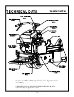
Страница 10: ...Operator Controls One piece all welded steel frame provides low center of gravity for maxi mum stability Familiarization with locations and operation of controls is necessary before attempting to ope...

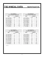
Страница 11: ...1 3 4 10 750 282 382 7 8 9 875 322 436 5 7 8 9 875 454 615 1 8 1 000 483 655 1 8 1 000 682 925 SAE GRADE 5 Fine Thread Zinc Plated SAE GRADE 8 Fine Thread Zinc Plated SIZE TORQUE SIZE TORQUE ft lbs Nm...

Страница 12: ...9 ZINC PLATED Coarse Thread Fine Thread SIZE Nm ft lbs Nm ft lbs M6 14 10 NA NA M8 34 25 35 26 M10 67 49 68 50 M12 117 86 125 92 M14 185 136 192 142 M16 285 210 295 218 M20 550 406 600 443 M24 950 70...

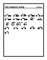
Страница 13: ...13 TECHNICAL DATA Hardware...

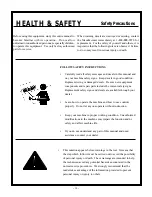
Страница 14: ...n Keep your machine in proper working condition Unauthorized modifications to the machine may impair the function and or safety and affect machine life If you do not understand any part of this manual...

Страница 15: ...is running or while it is still hot If fuel is spilled during refueling wipe it off from the engine immediately and discard the rag in a safe place Do not operate the equipment if fuel or oil leaks ex...

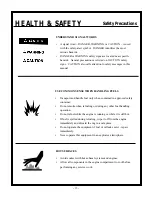
Страница 16: ...ed and latched during the operation close and latch cowl immediately after starting Keep hands clothing and jewelry away from all moving parts Keep all guards in place Never place your hands or any so...

Страница 17: ...ne elements that must be raised for service work Keep all parts in good condition and properly installed Repair damage immediately Replace worn or broken parts Remove any buildup of grease oil or debr...

Страница 18: ...to recover and recycle used air conditioning refrigerants Inquire on the proper way to recycle or dispose of waste from your local environmental or recycling center SAFETY DECALS FOR THE SAFETY OF YOU...

Страница 19: ...19 MAINTENANCE F IMPORTANT The person attempting any of the following maintenance tasks must be authorized to do so and have read and understood all sections within this manual Tasks...

Страница 20: ...ess and reliability on a job site Forks Four interchangeable adjustable fork options provide efficient handling of all types of loads Choose from round block forks or box forks for several different p...

Страница 21: ...n mark is recommended for general all temperature use Check daily for proper oil level DO NOT OVERFILL See Engine Owner s Manual for specifications ENGINE IS EQUIPPED WITH LOW OIL SHUTDOWN UNIT WILL S...

Страница 22: ...th engine running check the coupler between the engine and the hydraulic pump Do not make this inspection while engine is running It will be necessary to remove the inspection cover After adjusting an...

Страница 23: ...oil it is recommended to also change the hydraulic oil filter HYDRAULIC OIL FILTER Replace every 100 hours Never let the filter be completely clogged Use Stauff Filter P N 45150 CAUTION Never overfil...

Страница 24: ...at steering column every three 3 months or 50 hours Use lube oil on the directional control pivots sheave pins lift chains and tilt cylinder pins with engine oil every 3 three months or 50 hours Avoi...

Страница 25: ...Replace elements if damaged or excessively dirty SPARK PLUG Recommended spark plug BPR6ES NGK W20EPR U NIPPONDENSO To ensure proper engine operation the spark plug must be properly gapped and free of...

Страница 26: ...to avoid damage to the electrical system Keep batteries clean by wiping them with a damp cloth Keep all connections clean and tight Remove any corrosion and wash terminals with a solution of 1 part ba...

Страница 27: ...are extremely reliable and will ordinarily not need maintenance or repair If a vibration is experienced with engine running check the coupler between the engine and the hydraulic pump Do not make thi...

Страница 28: ...3 8 clearance between forward control lever and lever stop Continue to adjust control cable until clearance is achieved Make sure control bracket does not contact control bracket stop 3 Start machine...

Страница 29: ...ESULT IN SERIOUS INJURY OR DEATH WARNING WARNING WARNING Transmission Adjustment Brake Adjustment Brake Adjustments Brakes are adjusted at factory and will need to be adjusted as brake shoes wear Chec...

Страница 30: ...n 1 Position machine inner wheel over 2x4 and apply parking brake 2 Remove large tee bolt in center of wheel with crow bar figure 7 3 Remove outside wheel with quick change hub attached 4 Repeat above...

Страница 31: ...There are two ways of lifting the unit from the side or from the lifteye Lift hood to access lifteye Proper Tie Down Practices Tie unit down with proper devices Make sure all blocking is secure Proper...

Страница 32: ...and discarded at the end of the storage period together with the fuel filter element s 4 Operate the engine until it is warm Stop the engine and drain the lubricating oil from the oil pan 5 Preservat...

Страница 33: ...eners threads are clean and that you properly start thread engagement This will prevent them from failing when tightening Hoses Fittings and Leakage Check weekly for loose hose fittings damage and lea...

Страница 34: ...34 MAINTENANCE Periodic Maintenance Schedule...

Страница 35: ...35 MAINTENANCE Periodic Maintenance Schedule...

Страница 36: ...es 300 hours Hydraulic Oil 800 hours Hydraulic Filter 100 hours Hydraulic Breather 100 hours Battery monthly Grease Rear Tire Hub Steering Column weekly Grease Front Wheel Hubs yearly Lubricate Cables...

Страница 37: ...Fill tank Charge or replace Tighten clean terminals Tighten Lift Jockey will not move forward or reverse Low hydraulic oil Faulty hydraulic pump Faulty hydraulic drive Check level add if required Repl...

Страница 38: ......

Страница 39: ...ic Tank Assembly 52 53 Steering Handle Fuel Tank Assembly 54 55 Platform Brake Pedal Assembly 56 57 Brake Linkage Assembly 58 59 Wheel Motor Brake Tire Assembly 60 61 Quick Change Hub Assembly 62 63 H...

Страница 40: ...40 PARTS LIST Tilt Cylinder Front Cowl Assembly...

Страница 41: ...41 PARTS LIST Tilt Cylinder Front Cowl Assembly...

Страница 42: ...42 PARTS LIST Engine Cowl Assembly...

Страница 43: ...43 PARTS LIST Engine Cowl Assembly...

Страница 44: ...44 PARTS LIST Engine Assembly...

Страница 45: ...45 PARTS LIST Engine Assembly...

Страница 46: ...46 PARTS LIST Pump Assembly...

Страница 47: ...47 PARTS LIST Pump Assembly...

Страница 48: ...48 PARTS LIST Battery Hose Clamp Assembly...

Страница 49: ...49 PARTS LIST Battery Hose Clamp Assembly...

Страница 50: ...50 PARTS LIST Steering Housing Assembly...

Страница 51: ...51 PARTS LIST Steering Housing Assembly...

Страница 52: ...52 PARTS LIST Hydraulic Tank Assembly...

Страница 53: ...53 PARTS LIST Hydraulic Tank Assembly...

Страница 54: ...54 PARTS LIST Steering Handle Bar Fuel Tank Assembly...

Страница 55: ...55 PARTS LIST Steering Handle Bar Fuel Tank Assembly...

Страница 56: ...56 PARTS LIST Platform Brake Pedal Assembly...

Страница 57: ...57 PARTS LIST Platform Brake Pedal Assembly...

Страница 58: ...58 PARTS LIST Brake Linkage Assembly...

Страница 59: ...59 PARTS LIST Brake Linkage Assembly...

Страница 60: ...60 PARTS LIST Wheelmotor Brake Tire Assembly...

Страница 61: ...61 PARTS LIST Wheelmotor Brake Tire Assembly...

Страница 62: ...62 PARTS LIST Quick Change Hub Assembly...

Страница 63: ...63 PARTS LIST Quick Change Hub Assembly...

Страница 64: ...64 PARTS LIST Hand Foot Mast Control Assembly...

Страница 65: ...65 PARTS LIST Hand Foot Mast Control Assembly...

Страница 66: ...66 PARTS LIST Mast Assembly...

Страница 67: ...67 PARTS LIST Mast Assembly...

Страница 68: ...68 PARTS LIST Mast Assembly...

Страница 69: ...69 PARTS LIST Mast Assembly...

Страница 70: ...70 PARTS LIST Lift Frame Assembly...

Страница 71: ...71 PARTS LIST Lift Frame Assembly...

Страница 72: ...72 PARTS LIST Hydraulic Piping Schematic...

Страница 73: ...73 PARTS LIST Hydraulic Piping Schematic...

Страница 74: ...74 PARTS LIST Hydraulic Piping Schematic...

Страница 75: ...75 PARTS LIST Hydraulic Piping Schematic...

Страница 76: ...76 PARTS LIST Hydraulic System Schematic...

Страница 77: ...77 PARTS LIST Hydraulic System Schematic...

Страница 78: ...78 PARTS LIST Electrical Wiring Schematic...

Страница 79: ...79 PARTS LIST Electrical Wiring Schematic...

Страница 80: ...80 PARTS LIST 55398 Decal Identification...

Страница 81: ...er 7 55469 Decal Control Tilt 1 Hood LHS Control Lever 8 55471 Decal Caution Instruction LJ100 1 Hood Opposite Control levers 9 55472 Decal Warning Instruction LJ100 1 Hood Centered Above Handle 10 55...

Страница 82: ...82 PARTS LIST Decal Identification...

Страница 83: ...er 7 55469 Decal Control Tilt 1 Hood LHS Control Lever 8 55471 Decal Caution Instruction LJ100 1 Hood Opposite Control levers 9 55472 Decal Warning Instruction LJ100 1 Hood Centered Above Handle 10 55...

Страница 84: ......

Страница 85: ......

Страница 86: ......

Страница 87: ...FORNIA PROPOSITION 65 WARNING Operation of this equipment and or engine exhaust from this product contains chemicals known to the State of California to cause cancer birth defects or other repro ducti...

Страница 88: ...Be Stone Construction Equipment Inc P O Box 150 Honeoye New York 14471 Phone 800 888 9926 Fax 585 229 2363 e mail sceny stone equip com www stone equip com A 100 employee owned American manufacturer...

Отзывы: