


Owner’s Manual #513625
15
SU412 Model Machines
3.11 MIX INFORMATION
Mix can vary considerably from one manufacturer to
another. Differences in the amount of butterfat content
and quantity and quality of other ingredients have a
direct bearing on the fi nished frozen product. A change
in machine performance that cannot be explained by a
technical problem may be related to the mix.
Proper product serving temperature varies from one
manufacturer’s mix to another. Mixes should provide a
satisfactory product in the 20°F to 24°F range. Diet and
low-carb mixes typically freeze to proper consistency at
higher temperatures.
When checking the temperature, stir the thermometer in
the frozen product to get an accurate reading.
Old mix, or mix that has been stored at too high a tempera-
ture, can result in a fi nished product that is unsatisfactory.
To retard bacteria growth in dairy based mixes, the best
storage temperature range is between 33° to 38°F (0.5°
to 3.3° C).
3.12 OPERATION OF MIX PUMP
The mix pump switch is located at the front of the machine.
When a pump switch is placed in the ON position, the
mix pump motor will start pumping mix into the freezing
cylinder. When the set pressure is reached, the mix pump
will shut off automatically. When the switch is placed in
the OFF position, the mix pump will not operate.
NOTE
The mix pump motor is equipped with an internal
overload that will “trip”, disabling the pump when
the motor is overloaded. Consult the trouble shoot-
ing section for corrective information. The internal
overload will automatically reset after cooling. If
the condition continues, contact a qualifi ed service
person.
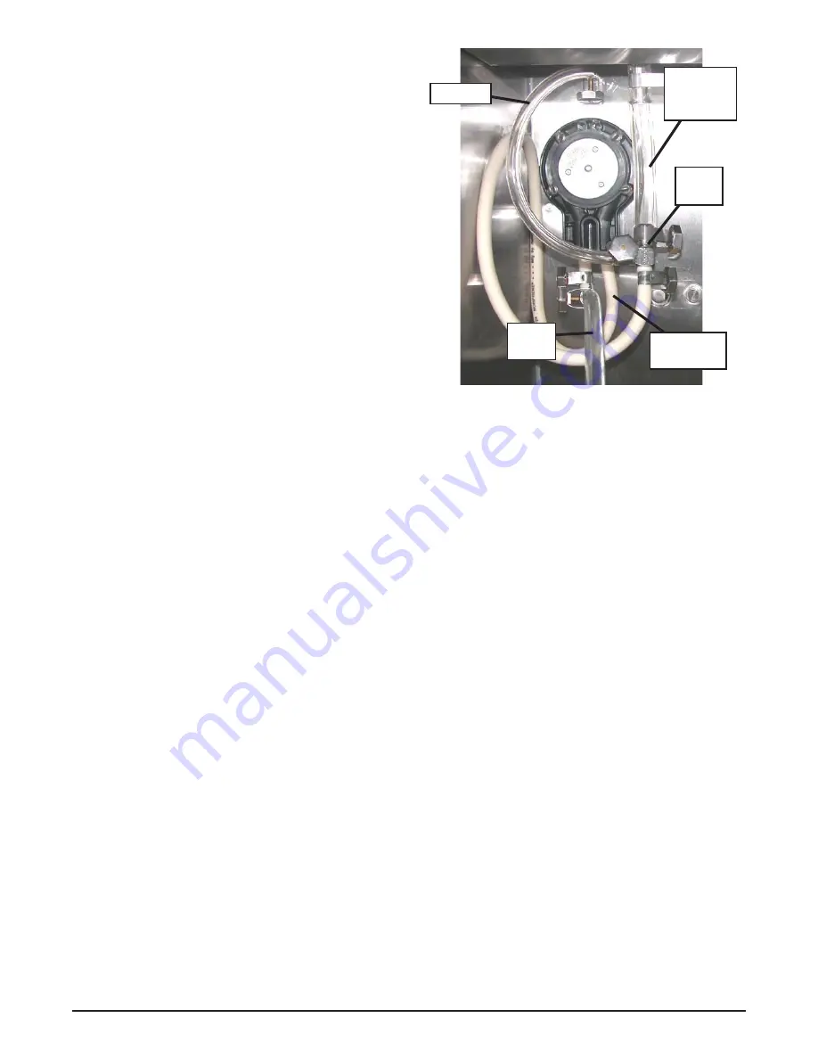
A.
Mix Operation: The peristaltic mix pump contains
one continuous mix pump hose. When looking at
the face of the peristaltic mix pump, the left side
of the hose is the mix intake or pickup. The right
side of the hose is the mix discharge. Mix is drawn
up the pickup side of the hose and transferred
through the discharge side to the machine (Fig.
3-10).
B.
Air Operation: The air compressor operates
whenever the peristaltic mix pump is running.
Air enters through a check valve on the piston
downstroke. The air is discharged through a
second check valve, on the piston upstroke. The
air and mix join at the tee and then travel to the
machine.
C.
The overrun adjustment is preset at the factory.
If an adjustment becomes necessary, refer to
Section 4.
3.13 MIX PUMP CLEANING
NOTICE
Any cleaning procedure must always be followed
by sanitizing before fi lling machine with mix. (Refer
to section 3.3)
The mix pump is approved for CIP (clean in place). It is
thoroughly cleaned when the detergent solution is pumped
through the machine. We recommend completely disas-
sembling the pump and disconnecting tubing every 14
days for inspection of parts to confi rm the CIP has been
properly performed. If any residue is detected, clean or
replace those parts as outlined below.
A.
Place the Main Power OFF/ON and Freezing
Cylinder OFF/ON switches in the ON position
and press the CLEAN button. Allow the auger to
agitate for 5 to 10 minutes.
B.
Remove the suction tube from the mix container.
Open the spigot to remove the mix remaining in
the freezing cylinder.
C.
Pump 2 gallons (7.5 liters) of potable water through
machine until the water comming out of the spigot
is clear.
D.
Pump 2 gallons (7.5 liters) of 90° to 110°F (32°C
to 43°C) detergent solution through the machine.
The use of soft water is recommended, along with
dishwashing detergents such as “Joy,” “Dawn,”
or equivalent.
E.
Place the mix pump switch in the OFF position.
Open the spigot to relieve the remaining pressure.
F.
Press the CLEAN button to stop the auger and
place the Main Power OFF/ON and Freezing
Cylinder OFF/ON switches in the OFF position.
Figure 3-10 Mix Pump Hose Routing
Air Line
Mix
Intake
Mix
Discharge
3-way
Tee
Air/Mix to
Freezing
Cylinder
Содержание SU412
Страница 1: ...Model SU412 OPERATORS MANUAL Manual No 513625 Rev 4...
Страница 2: ......
Страница 30: ...Owner s Manual 513625 26 SU412 Model Machines...
Страница 36: ...Owner s Manual 513625 32 SU412 Model Machines...