background image

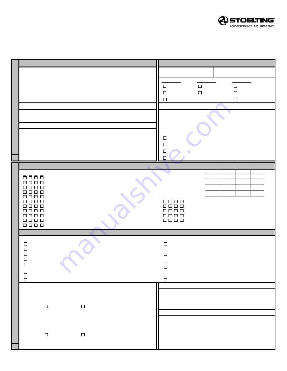
Custard Freezer Start-Up and Training Checklist

Distributor Instructions:

  Complete this form, obtain customer comments and signature and send to:

502 Hwy 67
Kiel  WI  53042

NOTE:  

A separate form must be submitted for each individual freezer.

BUYER INFORMATION

FREEZER INFORMATION (See freezer I.D. plate)

Installed at (business name):  ____________________________________

Contact person: _______________________________________________

Check one:

Check one:

Check one:

Address: ____________________________________________________

       115 volts

       single phase

       air-cooled

City: ________________________________________________________

       208 volts

       three phase

       water-cooled

State:________    Zip: __________    Phone: (       ) __________________

       230 volts

       air remote

DISTRIBUTOR INFORMATION

APPOINTMENT SCHEDULES

Business Name: _______________________________________________

Check-out/start-up scheduled for: ___/___/___ at _____AM/PM

Account Number: ______________________________________________

Appointments arranged by: ____________________________

AUTHORIZED SERVICE COMPANY (IF DIFF. THAN DISTR.)

with (buyer contact): _________________________________

Business Name: ______________________________________________

NOTE: 

Before leaving for appointment, phone to see that:

____________________________________________________________

       electrical complete

Address: ____________________________________________________

       water & drain complete (water-cooled)

City: ________________________________________________________

       mix, cones, cups, syrup, etc. available

A

State:________    Zip: __________    Phone: (       ) __________________

       trainee personnel available

CHECK-OUT START-UP CHECKLIST (Each column represents a freezing cylinder)

 1   2   3   4

(Check a column for each freezing cylinder)

Proper voltage, phase, breaker (check against nameplate)
Proper wire size per local code
High or unstable leg to L-2 (3-phase only)
Freezer level, front-to-back and side-to-side
Parts and accessories kit complete

1   2   3   4

Nuts, bolts, screws, electrical tight

Checked low pressure switch settings.

Drive belt tension/no lubricant leaks/check pulley and set screws

Locked thermostat settings.

Auger rotating counterclockwise

Water lines flushed before connection 

(W/C)

Checked pressures on high side, suction side and barrel.

Proper water and drain size 

(W/C)

Refrigeration level during operation (clear sight glass)

Proper clearance for air circulation 

(A/C Remote)

Checked alignment

TRAINING CHECKLIST

Check off as completed:

       Reviewed Owner's Manual with trainees.

       Check for auger seal, bearing & flight wear each time the 

       Reviewed Operator's Safety Precautions in Owner's Manual

       freezer is cleaned.

       Reviewed Warranty Shown in Owner's Manual

       Point out where Service Information Decal/Label is placed by 

       Disassemble, wash all parts, sanitize, lubricate & assemble.

       the Distributor or Service Contractor.

       Sanitize and start-up.

       Key points:  minimum mix level in hopper, etc.


Note: 

Sanitizing must be done immediately before starting freezer.

       Explain how foam in the hopper can prevent the low mix light

       Check product temperature ___________ °F, overrun _____________

       from illuminating.

       Shutdown and cleaning procedure.

       Discuss returning included survey if they choose.

LIST OF TRAINEES        - Name of Trainees -

Training conducted by:

___________________________________________________
___________________________________________________

Name: _________________________________  Date: _____/_____/_____

___________________________________________________

Check one:        Distributor                  Authorized Service Agency

SIGNATURE REQUIRED

Inspection/Checkout done by:

Inspection, check-out and operator training has been performed
on the above freezer. I have read and understand the warranty

Name: _________________________________  Date: _____/_____/_____

shown in the Owner's Manual.

Check one:        Distributor                  Authorized Service Agency

x _________________________________________________

    Signature, Buyer/Manager/Supervisor                    Date

Completed forms must be returned to Stoelting by mail, fax (800-545-0662), or email ([email protected]).

Form #721-064 Rev. 0

IMPORTANT:  

THIS SHEET MUST BE COMPLETED AND MAILED, FAXED, OR EMAILED WITHIN 30 DAYS

OF START-UP BY THE DISTRIBUTOR OR END-USER TO STOELTING IN ORDER TO REGISTER THE UNIT
UNDER WARRANTY.  IF WE DO NOT RECEIVE IT, WE CANNOT PROCESS FUTURE WARRANTY CLAIMS.

B

     Thi

s secti

on to be com

p

le

ted at i

n

stal

la

ti

on si

te.

Model No.

  Serial No.

Thi

s secti

on to be com

p

le

ted before vi

si

ti

ng si

te.

Actual Settings                    1            2            3            4

Supply Voltage
Head Pressure
Suction Pressure
Barrel Pressure

Содержание M202A

Страница 1: ...Model M202A Ser 0 25244 OPERATORS MANUAL Manual No 513614 Rev 5...

Страница 2: ......

Страница 3: ...built prior to date of change DO NOT ATTEMPT to operate the machine until instructions and safety precautions in this manual are read completely and are thoroughly understood If problems develop or q...

Страница 4: ...ecific safety information the following safety defini tions are provided to assist the reader The purpose of safety symbols is to attract your at tention to possible dangers The safety symbols and the...

Страница 5: ...00 57 1 Each Barrel Cleaning Brush Part BR 0030 1 Each Barrel Brush Handle Part BR 0035 4 Each 6 Casters Standard on Water Cooled Units 4 Each 6 Adjustable Stainless Steel Legs Std on Air Cooled Units...

Страница 6: ...of Hex Drive Anti Seize on the hex end of the beater shaft 2 Starting on the end of the beater shaft with the square tip place a metal spring arched up ward over the two pins closest to the end Place...

Страница 7: ...tion switch on the front of the machine is turned OFF the front control knob is to be in the OFF position 2 Remove the front gate and replace with splash guard Secure with wing nut The splashguard di...

Страница 8: ...exture Note If a growling noise comes from the machine during this procedure it may be an indication that there is not enough mix entering the barrel In crease the flow slightly by adjusting the flow...

Страница 9: ...t for approx 20 minutes This al lows the barrel enough time to warm before drain ing the remaining mix from the hopper 3 Take a sanitized bucket and place it at the opening of the front plate 4 Turn t...

Страница 10: ...2 Remove the front gate and front plate for washing Remove the o ring from the front plate Remove front bushing from beater shaft 3 Lay the washed parts out on a sanitized counter for air drying With...

Страница 11: ...tard is used 12 Return to the sink and wash each part Place in a rinse tank and then a sanitizing tank with a proper dilution of an approved sanitizer Cleaning and Disassembly NEVER USE HOT WATER ANY...

Страница 12: ......

Страница 13: ...tremely important that the following instructions be followed exactly each time the machine is disassembled for cleaning as part of nightly shutdown procedures Ross s makes no warranties expressed or...

Страница 14: ......

Страница 15: ...are subject to the conditions that Buyer a signs and returns to Stoelting upon installation the Checklist Warranty Registration Card for the affected equipment b gives Stoelting prompt written notice...

Страница 16: ...001 1332808 2...

Страница 17: ...s when installing line sets Seal the ends of the line sets during installation to prevent exposure to the atmosphere and foreign objects Blow the lines out with dry nitrogen to remove any debris that...

Страница 18: ...ale connector is 1 4 OD Solder a 5 16 line to the water valve inlet using silver solder the M202 requires a 1 4 line Install a shutoff valve in the water inlet line The drain connection is 1 1 2 Run a...

Страница 19: ...gram 6 Use an Allen wrench to open the shut off valves and release some of the nitrogen charge in the condensing unit The shut off valves are located on the outside of the condensing unit If no nitrog...

Страница 20: ...sters will be in a box located in the hopper pan A set of casters includes two casters with locks and two casters without locks Screw the casters into the threaded holes and tighten them using a pair...

Страница 21: ...ut leads going to the motor from the drive C Change the leads inside the motor electrical box 6 Check the refrigeration systems for leaks When pressurizing the system turn the refrigeration switch to...

Страница 22: ...suction line at the compressor and make sure the pressure is 25 psi Adjust the crankcase pressure regulator CPR if the pressure is not correct Remove threaded brass cap on the front of the CPR and ad...

Страница 23: ...er for the condensing unit 4 The refrigeration system for that barrel is set to warm for the mix Contact Ross service department and a technician can help adjust system properly 5 Condenser on remote...

Страница 24: ...ed in hopper is too warm 1 Make sure the hopper switch is on 2 Ranco temperature control located on the service side of the machine is set to warm Refer to the operating manual for proper settings 3 I...

Страница 25: ...d to check that the breaker for that outlet has not tripped If the breaker has tripped then reset and check dipping cabinet if it is running 2 Check condenser coil and make sure not plugged with dust...

Страница 26: ......

Страница 27: ...___ Diff 1 degree ________ Mode CL ________ Hold Cycle Temperature Control Note Temperature setting may be adjusted for your particular settings Stage 1 Factory Settings Your Settings F C F ________ T...

Страница 28: ...__________ Note each machine will differ slightly in preferred setting Condensing Unit Settings Air Cooled Units Location on each condensing unit Danfoss Head Pressure Control Adjustable at 255 PSIG H...

Страница 29: ...APPLICABLE The coils on the hopper dipping cabinet and remote condenser need to be cleaned to ensure proper airflow Use compressed air to clean the condensers Blow the air in the opposite direction of...

Страница 30: ......

Страница 31: ...ually Qty Front Wear Bushing X 2 C 2000 40 Large O Ring X 2 624782 Double Lip Shaft Seal X 2 SL 0010 KO Dirt Blaster Condenser Cleaner X 1 BL 0030 Blades X 16 C 2000 51 To order the replacement parts...

Страница 32: ......

Страница 33: ...enoid Barrel Refrigeration Solenoid Lemon Ice Option PUR Keyed Beater Switch Refrigeration Switch Barrel Hold Temp Control 240V COM Hopper Temp Control Lemon Ice Switch Pilot Light 240V COM L1 L2 L3 O...

Страница 34: ...off Valve Low Pressure Tap Head Pressure Regulator Set at 255 PSIG Differential Pressure Regulator Remote Air Cooled Condensing Unit 1 2 P High Pressure Switch Open 400 PSIG Close 300 PSIG 3 8 Pressur...

Страница 35: ...ater lines flushed before connection W C Checked pressures on high side suction side and barrel Proper water and drain size W C Refrigeration level during operation clear sight glass Proper clearance...

Отзывы: