


51
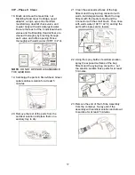
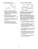
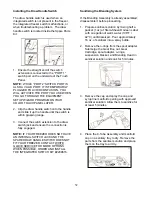
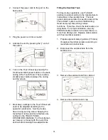
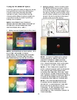
12. To position the Touch Panel closer or
further from the freezer operator, loosen the
base plate hand knobs and slide the
assembly forward or backward. Ensure the
anchor bracket is secured to all four posts of
the base plate. Tighten the hand knobs to
secure the desired position.
NOTE:
IF THE BACK SLOTS OF THE
ANCHOR BRACKET ARE NOT SECURED
TO THE BASE PLATE, THE TOUCH
PANEL MAY PUT TOO MUCH WEIGHT
ON THE FRONT OF THE ASSEMBLY,
CAUSING THE ASSEMBLY TO BECOME
UNSTABLE OR LOOSEN FROM THE
FREEZER.
13. To adjust the height or angle of the Touch
Panel, loosen the hex bolts and lock nuts
and move the Touch Panel into the desired
position. Tighten the bolts to secure.
14. Thread the ethernet cable through the
mounting bracket and back behind the
freezer.
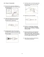
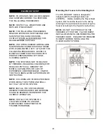
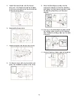
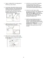
Draw Switch Options
When the draw spout is activated, the switch
relays the signal to the Flavor Burst
®
system,
telling it to activate the pumps and syrups as
product is drawn from the spout. The STL-
80BLD-INT includes two options for the draw
switch.
PREFERED METHOD: The draw switch
extension should be used with freezers with an
integrated switch already installed. If your
freezer does not have an integrated switch,
contact White Glove Service to order and install
the integrated switch kit #2209616.
OPTIONAL METHOD: The other option is a
draw handle switch. It is included in the Spare
Parts Kit for freezers lacking the internal switch.
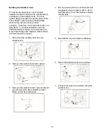
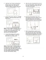
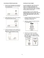
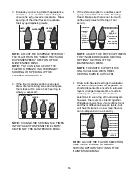
Installing the Draw Switch Extension
The draw switch extension is used with freezers
with an integrated switch already installed. This
is the recommended switch setup.
1. Ensure the straight end of the switch
extension is connected to the “PORT 1”
switch port on the underside of the Touch
Panel.
NOTE:
WHILE “PORT 2” SWITCH PORT IS
ALSO A VALID PORT, IT IS TEMPORARILY
PLUGGED TO AVOID CONFUSION. YOU
WILL ACTIVATE THE PORT YOU USE WHEN
YOU GO THROUGH THE EQUIPMENT
SETUP WIZARD PROGRAM ON YOUR
COLOR TOUCH PANEL LATER.
2. Connect the angled-end of the switch
extension to the switch jack underneath the
freezer overhang, near the draw handle.
3. Ensure the connections are fully engaged.
Содержание Flavor Burst
Страница 2: ......
Страница 9: ...6 PAGE INTENTIONALLY LEFT BLANK...
Страница 11: ...8 General System Overview Figure 1...
Страница 13: ...10 Integrated Cabinet Continued Figure 2...
Страница 17: ...14 Syrup Pump and Related Parts Figure 4...
Страница 19: ...16 Sanitizer Pump and Related Parts Figure 5...
Страница 21: ...18 Electronic Parts and Connections Continued Figure 6...
Страница 23: ...20 Spare Parts Kit Figure 7...
Страница 24: ...21 PAGE INTENTIONALLY LEFT BLANK...
Страница 36: ...33 PAGE INTENTIONALLY LEFT BLANK...
Страница 50: ...47 PAGE INTENTIONALLY LEFT BLANK...
Страница 75: ......
Страница 76: ......