Stereotaxis Niobe PM3.1 Скачать руководство пользователя страница 30

985-006001                                             REV. G                        Effective Date: 03 June 2008 


Stereotaxis, Inc. 

Page 29 of 43 

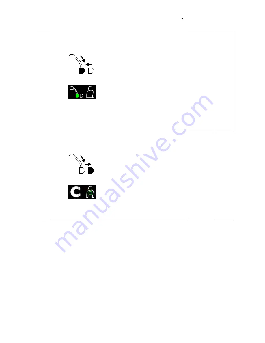
Verify the system will move to Retracted position from the Stowed 
position. 


While the Positioner is in the Stowed position press and hold 
the Retracted position button: 

 on the tableside controller until the Positioner 

reaches the Retracted position.  


Verify that the Retracted Position indicator: 

 is displayed on the control room and 

procedure room monitors. 


Verify that while the Positioner is moving the green indicator 
for the location the Positioner has been requested to move to 
blinks during the move. 


Verify that the total time to move to Retracted position does 
not exceed 60 seconds. 


P    F 


P    F 


P    F 


P    F 


Verify the system will move to Navigate position from the Retracted 
position. 


While the Positioner is in the Retracted position press and 
hold Navigate position button: 

 on the tableside controller until the Positioner 

reaches the Navigate position.  


Verify that the Navigate Position indicator: 

 is displayed on the control room and 

procedure room monitors. 


Verify that while the Positioner is moving the green indicator 
for the location the Positioner has been requested to move to 
blinks during the move. 


P    F 


P    F 


P    F 


Содержание Niobe PM3.1

Страница 1: ...EXHIBIT G Stereotaxis Installation Checklists ...

Страница 2: ...ion is correct prior to use Niobe MNS Installation Verification and Testing for PM3 1 Conversion to PM3 2 and for PM3 2 Conversion to PM3 1 4320 Forest Park Avenue Suite 100 St Louis MO 63108 USA 1 866 646 2346 1 314 678 6100 Manual P N 985 006001 www stereotaxis com Revision G Effective Date 03 June 2008 ...

Страница 3: ... Revised Pivot Force Verification R Ratliff 06 29 05 05 512 C Inclusion of Note for verification that a currently valid version of X ray Simulator is used S Ali 08 01 05 05 594 D Added line to X ray Simulator compatibility table J Hulsey 12 13 05 05 751 E Updated per Field Service markups J Thebeau 03 14 06 05 970 F Update for 22 Niobe software release Update per Field Service markups Add PM3 2 to...

Страница 4: ...ation Procedure 21 3 11 L Arm Lock Test Philips Allura Only 22 3 12 System Labeling Cosmetic Covers 23 3 13 Cover Scrape Tests 23 3 14 Post Installation Magnetic Survey 24 4 Verification of Conversion from PM3 2 to PM3 1 25 4 1 System Power On Off and Emergency Stop 25 4 2 PM3 1 System Movements Stowed Retracted and Navigate 27 4 3 Image Transfer from X ray Companion System 32 4 4 System Connectiv...

Страница 5: ...ough out this document It is required to use the version of X ray Simulator that is currently valid to avoid compatibility issues with the PM3CTRL software Compatibility Table for PM3CTRL and X ray Simulator X ray Simulator PM3CTRL VERSION S W P N VERSION S W P N V 2 10 Build 0 860 004466 10 V 3 32 and up 860 003000 25 and up V 2 9 Build 0 860 004466 9 V 3 31 and up 860 003000 24 and up V 2 8 Buil...

Страница 6: ...ner Use black or blue ink pens only Circle P F or N A in the Pass Fail column for each bulleted step in the test For each bulleted step in the test enter the tester s initials in the Initials column adjacent to the entry in the Pass Fail column Record software version numbers in the boxes provided Sign date and print your name in the appropriate spaces on signoff forms Check the appropriate boxes ...

Страница 7: ...g system nameplate labeling on cabinet and pods with nameplates included in system conversion kit 6 Perform verification tests in section 3 5 and 6 2 2 Convert from PM3 2 001 006000 1 to PM3 1 001 005000 1 Material Required Refer to system conversion kit 020 005451 2 Procedure 1 Turn off system power 2 Replace existing tableside controller 030 003972 3 with 030 003972 1 controller System power sho...

Страница 8: ...__ Alignment Fixture P N ____________________ Alignment Fixture S N ____________________ Calibration Certifier name ____________________ Calibration Certifier signature ____________________ Measured angles should be within 0 5 of commanded value Tilt Axis 0 Value ____________________ 15 Value ____________________ 15 Value ____________________ Cover Distance 0 15 15 Distance to Reference 247 65mm 5...

Страница 9: ..._________________ Calibration Certifier signature ____________________ Tilt Axis 0 Value ____________________ 15 Value ____________________ 15 Value ____________________ Cover Distance 0 15 15 Distance to Reference 247 65mm 5 1 5 mm ______ _______ _______ Distance to Reference 457 2mm 5 1 5 mm ______ _______ _______ Overall Alignment Calibration Set Up Pass Fail Test Performed by Signature _______...

Страница 10: ...er power on off button functions While the system is powered on the system Positioner power on light is lit actuate the on off switch by holding the button in the OFF position approx 3 sec until power is removed Verify that the on off light is no longer lit the red light labeled E Stop Active behind the right hand front door of the Control cabinet and the System Control Remote Stop Unit are exting...

Страница 11: ...8 Stereotaxis Inc Page 10 of 43 Figure 2 Table Side Controller with Graphics PM3 2 Version 001 006000 1 NOTE E Stop Button and or E Stop Light are not present on 001 005100 1 and 001 006100 1 configurations of Power Box or Table Side Controller ...

Страница 12: ... by observing the Homing Complete message on the monitors P F P F P F P F P F 3 4 PM3 2 System Movements Stowed Retracted Navigate AP Navigate RAO Navigate LAO and Navigate with Offset No Test Description Pass Fail Initials 4 Verify the system will move to Navigate AP position from the Stowed position While the Positioner is in the Stowed position press and hold Navigate AP position button on the ...

Страница 13: ...reaches the stowed position Verify that the Stowed Position indicator is displayed on the control room and procedure room monitors Verify that while the Positioner is moving the green indicator for the location the Positioner has been requested to move to blinks during the move Verify that the total time to move from Navigate to Stowed does not exceed 30 seconds Verify that the first 20 o of movem...

Страница 14: ...as been requested to move to blinks during the move Verify that the total time to move to Retracted position does not exceed 60 seconds P F P F P F P F 7 Verify the system will move to Navigate RAO and LAO positions from the Retracted position While the Positioner is in the Retracted position press and hold Navigate position button for Navigate RAO OR for Navigate LAO on the tableside controller u...

Страница 15: ...hes the Retracted position Verify that the Retracted Position indicator is displayed on the control room and procedure room monitors Verify that while the Positioner is moving the green indicator for the location the Positioner has been requested to move to blinks during the move P F P F P F 9 Now simultaneously hold the Image Transfer and the appropriate Movement button to initiate the interlock ...

Страница 16: ... to the AP position Press the Navigate LAO position button on the tableside controller and verify that the Positioner DOES move to the Navigate LAO position Press the Manual Retract buttons for the Left then the Right Pods to the Fully Retracted position Now simultaneously hold the Image Transfer and any Navigate button to initiate the interlock override condition and verify that the system will N...

Страница 17: ... Verify that the Retracted Icon is displayed if the tableside controller motion button is released prior to the movement being completed when Tilting Verify that you observed the following icon when you release the motion button prior to the requested position being achieved P F ...

Страница 18: ...ansfer image button on the display Verify that the system displays the image transfer in process icon same ICON as the transfer image except arrow goes to green and background goes to white Verify that the image is displayed on the Navigant TM monitor in two locations Verify that the transfer time is in the range of 3 5 seconds P F P F P F P F P F P F P F P F 14 Verify that the system will identif...

Страница 19: ...tional remove the Category 5 cable from connector on the front of each Galil motion controller in the Control cabinet Remove the connectors one at a time to verify that either connector will result in lost connectivity Verify that the system displays the red Cannot Communicate with the Magnet Positioners message ...

Страница 20: ... the navigation test apparatus Place the system in Navigate mode Select device type Select override Click on the Direction Navigation Mode icon Acquire two valid images Draw vectors for Cranial tip orientation CURSOR VECTOR POINTING TOWARDS YOU CUE LINE VECTOR POINTING AWAY FROM YOU REDUCED FIELD REGION APPROXIMATED Click the apply field button on the display and observe the catheter tip Verify th...

Страница 21: ...splayed on a THM 7025 are milliTesla P F P F P F 20 Verify that the Overlays can be toggled off on With valid vectors displayed select the Overlay Graphics On Off button on the display Verify that the graphic overlays are no longer displayed Select the Overlay Graphics On Off button on the display and verify that once again the graphic overlays are displayed P F P F P F 21 Verify that the Preset l...

Страница 22: ...e Artis or Allura with Niobe powered down Power up Artis or Allura and Niobe Enable both systems all E stop buttons OUT move Niobe to Stowed position Verify the X ray C arm can be moved the table can be moved and fluoro images can be obtained Place the Niobe magnets into navigate position Verify arbitrary magnetic fields can be applied Turn Niobe off Verify X ray C arm now moves at slow speed exer...

Страница 23: ...o Test Description Pass Fail Initials 24 Verify L arm HW circuit Power up both the Niobe and Allura systems Switch the LCD display to Niobe and login to the Niobe service panel Move the Allura L arm away from the head end position Move the magnet positioners to the Navigate position Verify on the service panel that the L arm is indicated as not locked Move the Allura L arm to the head end locked p...

Страница 24: ...sts No Test Description Pass Fail Initials 26 Verify that the system completes the scrape tests and that no interference between the covers and magnets is detected at Navigate AP Navigate RAO and Navigate LAO Apply proper Table C Arm positions to AVOID COLLISION Enter the system service mode Install and adjust the front covers on both positioners Move to the Navigate AP position Select the service...

Страница 25: ...r and stowed pod center locations and record on the site s elevation view drawing Label these reading with an a for above For identified spaces on the floor below measure at a height of approximately 2 meters from the floor the magnetic field strength at the isocenter and stowed pod center locations and record on the site s elevation view drawing Label these reading with a b for below Initial and ...

Страница 26: ...ee Figure 7 and verify that the red light labeled E Stop Active behind the left hand front door of the Control cabinet illuminates and all motion of the MPs is inhibited Verify the red light on the System control Remote stop is illuminated Philips system only While both the Niobe and Allura systems are powered on and operational depress the E stop button on the Allura TSO in the procedure room Ver...

Страница 27: ...ntrol Remote Stop Unit are extinguished and all motion of the MPs is inhibited While the system is powered off the system Positioner power on light is not lit actuate the on off switch to the on position Verify that the on off light illuminates the red light labeled E Stop Active behind the right hand front door of the Control cabinet and the System Control Remote Stop Unit are extinguished motion...

Страница 28: ...ot available at this time use the X ray simulator for testing purposes No Test Description Pass Fail Initials 1 Verify the system will move to Navigate position from the Stowed position While the Positioner is in the Stowed position press and hold Navigate position button on the tableside controller until the Positioner reaches the Navigate position Verify that the Navigate Position indicator is d...

Страница 29: ...hile the Positioner is in the Navigate position press and hold the stowed position button on the tableside controller until the Positioner reaches the stowed position Verify that the Stowed Position indicator is displayed on the control room and procedure room monitors Verify that while the Positioner is moving the green indicator for the location the Positioner has been requested to move to blink...

Страница 30: ...or the location the Positioner has been requested to move to blinks during the move Verify that the total time to move to Retracted position does not exceed 60 seconds P F P F P F P F 4 Verify the system will move to Navigate position from the Retracted position While the Positioner is in the Retracted position press and hold Navigate position button on the tableside controller until the Positione...

Страница 31: ... been requested to move to blinks during the move P F P F P F 6 Verify the system will move to Stowed position from Retracted While the Positioner is in the Retracted position press and hold the stowed position button on the tableside controller until the Positioner reaches the Stowed position Verify that the Stowed Position indicator is displayed on the control room and procedure room monitors Ve...

Страница 32: ...ssed F1 F2 F1 F2 P F P F P F P F 8 Verify that the C Arm Safe interface is operational between the Niobe and X ray Systems Place the Positioners in the Stowed position Move the C Arm until the C Arm is at 0 RAO LAO and 0 CRAN CRAD Press the Navigate position buttons on the tableside controller and verify that the system will move to the Navigate position Press the Retracted position button on the ...

Страница 33: ...n the Navigant TM monitor in two locations Verify that the transfer time is in the range of 3 5 seconds Take a second image or use the X ray simulator to send a file after moving the C Arm through at least 40 o of movement RAO LAO Click the Transfer image button on the display Verify that the system displays the image transfer in process icon same ICON as the transfer image except arrow goes to gr...

Страница 34: ...ime to verify that either connector will result in lost connectivity Verify that the system displays the red Cannot Communicate with the Magnet Positioners message P F 4 5 Drawing Vectors Apply Field Reduce Field No Test Description Pass Fail Initials 1 Verify that you can draw a vector on Valid Images and apply the field Mount a catheter on the table in the navigation test apparatus Place the sys...

Страница 35: ...la P F P F 3 Verify that the Tableside Controller Apply Field and Reduce Field function Repeat 1 catheter tip orientation from test 19 but use the Tableside Controller apply field button Verify that the fields were applied Repeat test 20 but use the Tableside Controller Reduce Field button 1 Verify that the field was reduced P F P F P F P F 4 Verify that the Overlays can be toggled off on With val...

Страница 36: ...prior to Device History Record DHR Release of the system Ability to use Artis with Niobe powered down Power up Artis and Niobe Enable both systems all E stop buttons OUT Verify the X ray C arm can be moved the table can be moved and fluoro images can be obtained Place the Niobe magnets into navigate position Verify arbitrary magnetic fields can be applied Turn Niobe off Verify X ray C arm now move...

Страница 37: ...obe E stop buttons Verify X ray recognizes the E stop condition For Philips systems only Power up Niobe and Allura systems are in normal operating state Verify the X ray C arm can be moved the table can be moved and fluoro images can be obtained Move the Niobe to Stowed position Shut down the Niobe with the Shutdown System button on the Navigant UI Verify the X ray C arm can be moved the table can...

Страница 38: ...l shift or convergence occurs when viewed from approximately one meter Verify that the NWS user interface is displayed on both the procedure room and control room monitors Verify that the same interface is displayed at both locations Right click on the desktop background on the NWS computer Click Properties Click the Settings tab Verify that the Color Palette indicates at least 32 bits Verify that...

Страница 39: ...ackground and left clicking on Properties Close the window P F P F P F 35 Verify spare USB ports in the procedure room Temporarily disconnect the mouse from the USB remote extender in the procedure room The USB remote extender hub may be located in the floor box adjacent to the patient table or in on the table base itself Plug the mouse back into each of the un used spare USB ports in the control ...

Страница 40: ...stem Verification Testing Partial Figure 4 Cardiodrive User Interface E Stop Button Step selection switch 1mm or 3mm Advance Retract Joystick Retract push button Retract indicator light Advance indicator light Select push button Power indicator light Select indicator light Advance push button ...

Страница 41: ...and Power indicator lights on the control room Cardiodrive User Interface are illuminated While the system is powered on and operational and the control room Cardiodrive User Interface is selected verify that the tableside Cardiodrive User Interface Select and Power indicator lights are not illuminated P F P F 40 NOTE Customer may have purchased a system with a tableside Cardiodrive User Interface...

Страница 42: ...nal depress the tableside Cardiodrive User Interface select button and select the 3 mm movement Depress the Advance button and verify that the catheter advances 3mm and verify the Advance indicator light illuminates Depress the Retract button and verify the catheter retracts 3mm and the Retract indicator light illuminates Select the 1mm movement Depress the Advance button and verify that the cathe...

Страница 43: ... Lock Test Philips Allura Only P F N A 3 12 System Labeling and Cosmetic Covers P F N A 3 13 Cover Scrape Tests P F N A 3 14 Post installation Magnetic Survey P F N A 4 Verification of Conversion from PM3 2 to PM3 1 4 1 System Power On Off and Emergency Stop P F N A 4 2 PM3 1 System Movements Stowed Retracted and Navigate P F N A 4 3 Image Transfer from X ray Companion System P F N A 4 4 System Co...

Страница 44: ... installed and we can verify joint functionality I hereby certify that the Niobe Magnetic Navigation System is installed and functioning within published specifications Stereotaxis Sign off Sign Name ______________________ Date _______________ Print Name ______________________ Return the original of this completed document along with all attachments to Quality Assurance Department ...

Страница 45: ...on Procedure Page 1 of 19 WARNING This is a revision controlled document Verify revision is correct prior to use Stereotaxis Inc Confidential Vdrive Vdrive Duo Installation Test and Verification Procedure 4320 Forest Park Avenue Suite 100 St Louis MO 63108 USA 1 866 646 2346 1 314 678 6100 WWW Stereotaxis com ...

Страница 46: ... applies to verifying the proper installation of the Vdrive and Vdrive Duo for Stereotaxis Inc service personnel 3 APPLICABLE DOCUMENTS 001 002307 1 BOM Vdrive System 001 002307 2 BOM Vdrive Duo System 907 002307 RMS Interconnect Diagram 986 002307 RMS Shipping Instructions HDW 0210 RMS Installation Procedure 001 002542 1 Vdrive Variable Loop Disposable Set HDW 295 Vdrive User Guide 4 DEFINITIONS ...

Страница 47: ...ment Instructions Facility Name Facility Street Address Facility City State Zip Lab Number Facility Contact Name Contact Title Phone Number for Contact Lab Phone Number or Ext Niobe NWS Niobe System Serial Number ___________ NWS S W Version _________________ Niobe S W Version _________________ Vdrive or Vdrive Duo Select One System Serial Number _________________ RMS Control Box Serial ___________...

Страница 48: ...try in the Pass Fail column Record software version numbers where requested Sign date and print your name in the appropriate spaces on signoff forms 7 Mechanical Installation and Upgrade for RMS and OBUI Test Description Pass Fail Initials Complete the Installation of the system Complete upgrade Installation of the Control Cabinet 030 003980 as detailed in the Installation Manual document number H...

Страница 49: ...fy revision is correct prior to use Stereotaxis Inc Confidential 8 Power On Home Vdrive Test Description Pass Fail Initials Power on Power on Niobe and Odyssey Systems All E Stops are pulled out de activated Power indicator lights on Vdrive control box are on Illuminated AC Power This is not as bright as the DC insdicator light DC Power Niobe Status P F P F P F P F ____ ____ ____ ____ ...

Страница 50: ...Initials Homing the Vdrive Select the Vdrive tab on the OBUI Homing button appears When Homing is complete Ready to Load Handle Clamps appears Selecting this button moves the drive unit to loading position Attach Handle Clamp assy For a Vdrive Duo system attached the Handle Clamp assy to Drive Unit A Please Wait Checking Disposable Validity appears on screen For a Vdrive Duo system attach the Hand...

Страница 51: ...t Description Pass Fail Initials Testing movements from OBUI If testing a Vdrive Duo system attach the Handle Clamps to Drive Unit A Advance Vdrive Handle Clamps advance Retract Vdrive Handle Clamp Retract Advance Rear Catheter Clamp Advances Rear Catheter Clamp Retract Rear Catheter Clamp Retracts Rear Catheter Clamp Navigate Control Allows function of the mouse controller in Control Room The fol...

Страница 52: ... a Vdrive Duo system remove the Handle Clamps from Drive Unit A and reinstall on Drive Unit B Advance Vdrive Handle Clamps advance Retract Vdrive Handle Clamp Retract Advance Rear Catheter Clamp Advances Rear Catheter Clamp Retract Rear Catheter Clamp Retracts Rear Catheter Clamp Navigate Control Allows function of the mouse controller in Control Room The following screen should now be displayed P...

Страница 53: ...Setup of Vdrive in Navigant Navigate Control was selected on OBUI moving control of Vdrive to Control Room 3D Connexion Mouse Twist Knob Right Motor Turns Clockwise Twist Knob Left Motor Turns Counter Clockwise Push or Tilt Knob Forward Drive Unit moves Forward Advance Catheter Push or Tilt Knob Back Drive Unit Moves Back Retract Catheter Tilt or Push Knob Right Drive Moves Forward Deflects Cathet...

Страница 54: ...age 10 of 19 WARNING This is a revision controlled document Verify revision is correct prior to use Stereotaxis Inc Confidential Test Description Pass Fail Initials Push the Button Moves the Blue Drive Counter Clockwise Lasso Loop Larger Push the button Moves Blue Drive Counter Clockwise Lasso Loop Smaller P F P F ____ ____ ...

Страница 55: ...ect Settings Select Navigant Tab In the Please Select Window drop down Select Nav Fluoro A any selection will work Test Description Pass Fail Initials Setup of Vdrive in Navigant RMS HUD box is unchecked Check the box for RMS HUD Select OK The Vdrive Motion is now displayed on the screen Push or Tilt Knob Forward Indicator on Display moves Push or Tilt Knob Back Indicator on Display moves Push or ...

Страница 56: ... Stops are de activated Pulled out and the Vdrive Icon on the Navigant Screen displays the following The E Stop button is Pulled up De Activated on the Vdrive Control Box and The Red E Stop indicator Light is off The E Stop button is pulled up De Activated on the Niobe On Off Box and The Red E Stop indicator Light is off The following screen is displayed on the OBUI Tableside Controller Activate P...

Страница 57: ... Illuminated Pull out De Activate the E Stop on the Vdrive Control Box The Red E Stop Light is Not Illuminated The E Stop Active is Not Displayed on the OBUI The Vdrive Icon on Navigant Displays Push in Activate the E Stop on the Tableside Controller The Red E Stop light on the Vdrive Control Box is illuminated The E Stop is Active is displayed on the OBUI The Red E Stop Light on the Niobe On off ...

Страница 58: ...p Active is Not Displayed on the OBUI The Red E Stop Light on the Niobe On Off box is Not Illuminated The Vdrive Icon on Navigant Displays Push in Activate the E Stop on the Niobe On Off Box The Red E Stop Light on the Niobe On off box is illuminated The V Drive E Stop Icon on Navigant is displayed The Red E Stop Light on the Vdrive Control Box is illuminated The E Stop is Active is displayed on t...

Страница 59: ...f 19 WARNING This is a revision controlled document Verify revision is correct prior to use Stereotaxis Inc Confidential Test Description Pass Fail Initials The Vdrive Icon on Navigant Displays The E Stop Active is Not Displayed on the OBUI The Red E Stop Light on the Vdrive Control Box is Not Illuminated P F P F P F ____ ____ ____ ...

Страница 60: ... Stop If this is a Siemens system select N A and skip this section Vdrive E Stop is de activated Pulled out and the Vdrive Icon on the Navigant Screen displays the following The Red E Stop indicator Light is off on the Vdrive Control Box The following screen is displayed on the OBUI Tableside Controller Activate Push down the E Stop Switch on the Vdrive Control Box The Red E Stop indicator Light i...

Страница 61: ...t Description Pass Fail Initials The E Stop Active Icon is displayed on Navigant De Activate Pull Out the E Stop button on the Vdrive Control Box The Red E Stop indicator Light is off on the Vdrive Control Box the Vdrive Icon on the Navigant Screen displays the following The E Stop Active is No Longer Displayed on the OBUI Tableside Controller The following screen is displayed on the OBUI Tablesid...

Страница 62: ...y P F 10 Vdrive movement from OBUI Screen P F 11 Vdrive Movement from Control Room 3D Connexion Mouse P F 12 Setup and Test from Navigant P F 13 E Stop Functionality Siemens P F N A 13 1 E Stop Functionality Philips P F N A I hereby certify that the Niobe Magnetic Navigation System is installed and functioning within published specifications Stereotaxis Sign off Sign Name _________________________...

Страница 63: ... controlled document Verify revision is correct prior to use Stereotaxis Inc Confidential 15 REVISION HISTORY REVISION ECO DATE BRIEF DESCRIPTION AUTHOR A 10 414 2 8 2010 New Release R Hitchens B 11 034 03 09 11 Updates A Miller C 11 585 10 Nov 2011 Update to include Vdrive Duo B Kidd D 12 073 07 24 2012 Add additional site information Edit for Clarity A Miller ...

Страница 64: ...RNING This is a revision controlled document Verify revision is correct prior to use Stereotaxis Inc Confidential Odyssey Quad HD System Installation Verification and Testing 4320 Forest Park Avenue Suite 100 St Louis MO 63108 USA 1 866 646 2346 1 314 678 6100 Manual P N 985 007011 www stereotaxis com Revision A Revision Date 08 07 2012 ...

Страница 65: ... HD System Installation Verification and Testing Page 2 of 19 WARNING This is a revision controlled document Verify revision is correct prior to use Stereotaxis Inc Confidential REVISION HISTORY Rev Description Author Date ECO A Initial release K Eversman 08 07 2012 12 286 ...

Страница 66: ...fication 8 3 2 1 Insulation from Building Steel or Ground 8 3 2 3 Electrical Safety Verification Summary 14 3 3 Odyssey Quad HD System Verification 15 4 Peripheral Functionality 18 4 1 Required Equipment 18 4 2 Procedure 18 5 Odyssey Quad HD System Verification Checklist 19 6 Installation Complete Checklist 19 List Of Figures FIGURE 1 INSULATION FROM BUILDING STEEL OR GROUND TEST SETUP 10 FIGURE 2...

Страница 67: ...m Configuration Quad HD Quad Quad Installed with Niobe S N or Std Lab Installed with Cinema S N or N A X Ray System Lab Room ID Lab Phone Number Extension Facility Name Facility Street Address Facility City State Zip Facility Contact Name Facility Contact Job Title Contact Phone Number This document should be completed in the following manner Use black or blue ink pens only Circle P F or N A in th...

Страница 68: ...room preparation defect Equipment Required Digital Volt Meter Hand tools as required such as screwdrivers etc to enter electrical panels and junction boxes Danger High voltages are present in electrical distribution panels Only competent qualified personnel should open electrical panels for inspection Always consult with customer s electrical contractor and or building maintenance personnel before...

Страница 69: ...ailable use Table 1 to record the measurements If a Neutral wire is NOT available use Table 2 to record the measurements With the panel cover off reconnect power and perform the following measurements 10 of expected is acceptable Actual L G _____VAC L N _____VAC N G _____VAC N G _____Ω US Installs Expected Voltages L G 120VAC L N 120VAC N G 3 0VAC N G 1Ω Tolerances Met Yes No EU non standard US In...

Страница 70: ...G This is a revision controlled document Verify revision is correct prior to use Stereotaxis Inc Confidential Disconnect power from the panel Replace panel cover Measurements Performed by Signature ___________________________________ Date ____________ Print Name __________________________________ Company Name ______________________________ ...

Страница 71: ...D UPS OFF and then the Odyssey Quad HD system OFF Switch the main circuit breaker or disconnect feeding the Odyssey Quad HD system OFF so NO power is applied to the Odyssey Cabinet Disconnect the following cables on the Odyssey Quad HD Cabinet that connect to the Niobe System If Applicable and X ray System W663 from MDM A1 Input 27 Niobe VGA cable W664 from Router A9 Port 2 Niobe system Ethernet c...

Страница 72: ...ster between the disconnected Protective Earth ground wire and the Odyssey Cabinet ground bus bar see notes 1 through 4 and Figure 1 Setup Adjust settings on MegaOhm HiTester prior to connecting any wires for measurement o Set the function selector to 500 V o Use the COMP key to select the 2 MOhm comparator setting o The buzzer will sound when the insulation resistance measurement is less than 2 M...

Страница 73: ...und wire and the Odyssey Cabinet copper bus bar Test leads Facility Power Disconnect Panel Oyssey Quad HD Cabinet This must be a non conductive conduit connection to ensure isolation Figure 1 Insulation from Building Steel or Ground Test Setup NOTE 1 Verify the cables that connect between Odyssey Niobe and Odyssey X ray system are disconnected NOTE 2 Verify that the Odyssey Procedure Room Hub is i...

Страница 74: ...th resistance see Figure 2 with the HYAMP III model 3130 between the Ground Bus Bar and the Odyssey accessible conductive parts Cabinet Control Room Monitor Procedure Room Hub and Procedure Room Monitor GND VOLTAGE SELECTOR CAL REMOTE INTERFACE OPTION SIGNAL OUTPUT SIGNAL INPUT T6 3A 250V LINE INPUT CURRENT RETUR N INTERCONNEC T 115V 230V 6 3A MAX 50Hz 60Hz CAT II INTERLOCK ODYSSEY CABINET Odyssey...

Страница 75: ...to one end of the external test wire to be used to connect the HYAMP III to the Stereotaxis equipment Connect the P N 05002D 24 Cable Assembly High Current to the other end of the external test wire to be used to connect the HYAMP III to the Stereotaxis equipment Press the Menu button twice Press the Test button on the menu V down arrow 5 times to point to the offset parameter Press the Edit butto...

Страница 76: ...cation Summary On the HYAMP III Model 3130 press the red pushbutton labeled RESET Move the 05002D 37 RETURN with test wire cable to the Procedure Room Hub On the HYAMP III Model 3130 press the green pushbutton labeled TEST The ground bond test will now take place for 120 seconds Move the 05002D 37 RETURN with test wire cable to the Procedure Room Monitor if applicable On the HYAMP III Model 3130 p...

Страница 77: ...HiTester Ground Bond Tester Test Results Safety Test Test Result Test Limit Pass Fail NA Insulation _____ MegaOhm 2 MegaOhm Ground Bond Tester Verification N A N A Cabinet Earth Resistance _____ milliohm 100milliOhm Control Room Monitor Earth Resistance _____ milliohm 100milliOhm Procedure Room Hub Earth Resistance _____ milliohm 100milliOhm Procedure Room Monitor Earth Resistance _____ milliohm 1...

Страница 78: ...ure Room Hub right side where the cables enter P F P F P F _____ _____ _____ 3 Verify Navigant Software Versions Start the Odyssey system and record the Navigant software version that is located on the main menu window _______________________________________________ For MDM Software Version End the Navigant software Ctrl Alt Del at task manager select the Applications tab and locate Navigant Works...

Страница 79: ...rify that no visible pixel jitter pixel shift or convergence occurs when viewed from approximately one meter Verify that the Odyssey user interface is displayed on all applicable monitors Verify that the same interface is displayed on all applicable locations P F P F P F _____ _____ _____ 5 Verify Odyssey On Off functions While the Odyssey System is powered on power down the lab in the following s...

Страница 80: ... 003004 X CD Using the values provided by the Odyssey Network Administrator set the values of the hospital name and lab by entering them into the SiteName and LabNumber fields of this file The following is an example the values shown below are an example only use the values provided to you that are specific to the site SiteName Baptist Hospital North LabNumber 1 Save the file and exit NOTEPAD Rebo...

Страница 81: ...XML Name MDM Channel USB Number USB IP Address MAC Addr TPI S N Test Result 1 Live Flouro A 3 1 192 168 168 30 19 Pass Fail N A 2 Live Flouro B CR9 19 2 192 168 168 31 22 Pass Fail N A 3 Live ECG CR1 21 3 192 168 168 32 18 Pass Fail N A 4 Review ECG CR2 12 3 192 168 168 33 15 Pass Fail N A 5 Carto CR3 1 5 192 168 168 34 1C Pass Fail N A 6 Ultrasound PR1 4 6 192 168 168 35 13 Pass Fail N A 7 Ref Fl...

Страница 82: ..._______ Company Name ______________________________ 6 Installation Complete Checklist Section Description Pass Fail Initials 2 Site Information and Document Instructions P F 3 1 Electrical Power System P F 3 2 Electrical Safety Verification P F 3 3 Odyssey Quad HD System Verification P F 4 Peripheral Functionality P F N A Item Yes No Initials Installation Completed in Accordance with HDW 0188 Odys...

Страница 83: ...NING This is a revision controlled document Verify revision is correct prior to use Stereotaxis Inc Confidential Odyssey Cinema TM Studio System Installation Verification and Testing 4320 Forest Park Avenue Suite 100 St Louis MO 63108 USA 1 866 646 2346 1 314 678 6100 Manual P N 985 007842 www stereotaxis com Revision C Revision Date 21 May 2012 ...

Страница 84: ... J Farrar 24 August 2011 11 481 B Revised following first usage T Barrett NVSIA L Klingler 23 September 2011 11 532 C Updates for Cinema 1 5 J Morrow 21 May 2012 12 179 Table of Contents 1 Introduction 3 3 Odyssey Cinema Studio System 4 3 1 Electrical Power System 4 3 2 Odyssey Cinema Studio System Verification 4 3 3 Odyssey Cinema Studio Telepresence Verification If Available 6 3 4 Odyssey Cinema...

Страница 85: ...System Serial Number Installed with Cinema S N Installed with Odyssey HD Odyssey Quad Link S N X Ray System Facility Name Facility Street Address Facility City State Zip Facility Contact Name Facility Contact Name s Job Title Phone Number for Contact Lab Room ID Lab Phone Number This document should be completed in the following manner Use black or blue ink pens only Circle P F or N A in the Pass ...

Страница 86: ... cords are capable of connection to building power outlets Odyssey Cinema Studio requires a surge protected power strip with at least six outlets Confirm that this has been supplied P F _____ 3 2 Odyssey Cinema Studio System Verification No Test Description Pass Fail Initials 1 Verify installation of Odyssey Cinema Studio per document HDW 0289 has been completed P F _____ 2 Confirm the Telepresenc...

Страница 87: ...ma Proxy Icon on the Desktop and record the Odyssey Link software version here _______________________________________________ In a browser e g Internet Explorer enter the URL address http 127 0 0 1 4011 without quotes then hit ENTER Verify the Remote Service page appears with the correct site and lab identification Scroll down to the bottom to see the version and record it here __________________...

Страница 88: ...s Media Center Confirm audio is heard Confirm the Headset microphone functions Confirm the Webcam functions Start it and confirm webcam video is displayed Confirm the Speakers function P F P F P F P F P F P F _____ _____ _____ _____ _____ _____ 3 3 Odyssey Cinema Studio Telepresence Verification If Available No Test Description Pass Fail Initials 1 Initiate a Telepresence connection between the St...

Страница 89: ...uipment at the Colo can only be connected to one customer at a time P F _____ 2 Using Studio play a sample video clip using Windows Media Player Set the clip on repeat and drag the media player window to the Transmit display Verify Video Clip is Displayed P F _____ 3 VNC to the Colo Broadcast PC at 10 196 0 23 Password magnet Log in to the desktop User Name OdysseyBAS Password magnet Start Cinema ...

Страница 90: ...axis Inc Confidential 3 5 Odyssey Cinema Studio System Verification Checklist Section Description Pass Fail Initials 3 3 Odyssey Studio System Verification Testing P F I hereby certify that the Odyssey Cinema Studio System is installed and functioning within published specifications Signature _______________________________ Date ____________________ Print Name _______________________________ Compa...

Страница 91: ...Power System P F 3 2 Odyssey Cinema Studio System Verification P F 3 3 Odyssey Cinema Studio Broadcast Verification P F Item Yes No Initials Installation Completed in Accordance with HDW 0289 Odyssey Studio Installation Manual Note Ensure a completed Appendix D of 985 007802 is attached to this document Y N Signature Date Print Name Company Name Return a copy of the completed sections of this docu...

Отзывы: