background image

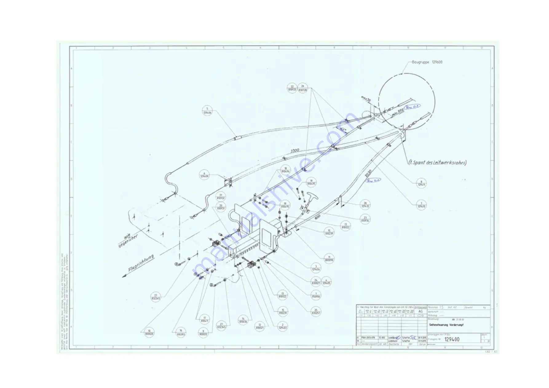
D) FLIGHT CONTROLS: RUDDER CONTROL

Содержание S12

Страница 1: ......

Страница 2: ...g Phone 49 3341 3612 0 E mail info stemme de Web www stemme com All rights reserved Reproduction or disclosure to third parties of this document any part there of is not permitted except with the prior and express written permission of STEMME AG DOCUMENT NUMBER L500 912 820 ISSUE JUL 20 2016 AMENDMENT 00 DATE CHAPTER PAGE 0 2 MAINTENANCE MANUAL STEMME S12 ...

Страница 3: ......

Страница 4: ...DOCUMENT NUMBER L500 912 820 ISSUE JUL 20 2016 AMENDMENT 00 DATE CHAPTER PAGE 0 4 MAINTENANCE MANUAL STEMME S12 THIS PAGE IS INTENTIONALLY LEFT BLANK ...

Страница 5: ... 2016 0 20 00 JUL 20 2016 CHAPTER 1 1 1 00 JUL 20 2016 1 2 00 JUL 20 2016 1 3 00 JUL 20 2016 1 4 00 JUL 20 2016 1 5 00 JUL 20 2016 1 6 00 JUL 20 2016 CHAPTER 2 2 1 00 JUL 20 2016 2 2 00 JUL 20 2016 2 3 00 JUL 20 2016 2 4 00 JUL 20 2016 2 5 00 JUL 20 2016 PAGE APPROVED AM NO DATE 2 6 00 JUL 20 2016 2 7 00 JUL 20 2016 2 8 00 JUL 20 2016 CHAPTER 3 3 1 00 JUL 20 2016 3 2 00 JUL 20 2016 3 3 00 JUL 20 2...

Страница 6: ... 20 2016 3 61 00 JUL 20 2016 3 62 00 JUL 20 2016 CHAPTER 4 4 1 X 00 JUL 20 2016 4 2 X 00 JUL 20 2016 4 3 X 00 JUL 20 2016 4 4 X 00 JUL 20 2016 4 5 X 00 JUL 20 2016 PAGE APPROVED AM NO DATE 4 6 X 00 JUL 20 2016 CHAPTER 5 5 1 00 JUL 20 2016 5 2 00 JUL 20 2016 5 3 00 JUL 20 2016 5 4 00 JUL 20 2016 5 5 00 JUL 20 2016 5 6 00 JUL 20 2016 5 7 00 JUL 20 2016 5 8 00 JUL 20 2016 5 9 00 JUL 20 2016 5 10 00 J...

Страница 7: ... JUL 20 2016 7 10 00 JUL 20 2016 7 11 00 JUL 20 2016 7 12 00 JUL 20 2016 7 13 00 JUL 20 2016 7 14 00 JUL 20 2016 7 15 00 JUL 20 2016 PAGE APPROVED AM NO DATE 7 16 00 JUL 20 2016 7 17 00 JUL 20 2016 7 18 00 JUL 20 2016 7 19 00 JUL 20 2016 7 20 00 JUL 20 2016 7 21 00 JUL 20 2016 7 22 00 JUL 20 2016 7 23 00 JUL 20 2016 7 24 00 JUL 20 2016 7 25 00 JUL 20 2016 7 26 00 JUL 20 2016 7 27 00 JUL 20 2016 7 ...

Страница 8: ...0 2016 ANNEX C C 1 00 JUL 20 2016 C 2 00 JUL 20 2016 ANNEX D D 1 00 JUL 20 2016 PAGE APPROVED AM NO DATE D 2 00 JUL 20 2016 D 3 00 JUL 20 2016 D 4 00 JUL 20 2016 D 5 00 JUL 20 2016 D 6 00 JUL 20 2016 D 7 00 JUL 20 2016 D 8 00 JUL 20 2016 D 9 00 JUL 20 2016 D 10 00 JUL 20 2016 D 11 00 JUL 20 2016 D 12 00 JUL 20 2016 D 13 00 JUL 20 2016 D 14 00 JUL 20 2016 D 15 00 JUL 20 2016 D 16 00 JUL 20 2016 ANN...

Страница 9: ...1 00 JUL 20 2016 F 22 00 JUL 20 2016 F 23 00 JUL 20 2016 F 24 00 JUL 20 2016 F 25 00 JUL 20 2016 F 26 00 JUL 20 2016 F 27 00 JUL 20 2016 F 28 00 JUL 20 2016 F 29 00 JUL 20 2016 F 30 00 JUL 20 2016 F 31 00 JUL 20 2016 F 32 00 JUL 20 2016 F 33 00 JUL 20 2016 F 34 00 JUL 20 2016 F 35 00 JUL 20 2016 F 36 00 JUL 20 2016 F 37 00 JUL 20 2016 F 38 00 JUL 20 2016 PAGE APPROVED AM NO DATE ...

Страница 10: ...DOCUMENT NUMBER L500 912 820 ISSUE JUL 20 2016 AMENDMENT 00 DATE CHAPTER PAGE 0 10 MAINTENANCE MANUAL STEMME S12 THIS PAGE IS INTENTIONALLY LEFT BLANK ...

Страница 11: ...ckpit 3 2 3 2 1 General 3 2 3 2 2 Control Elements and Instruments 3 3 3 2 3 Controls at the Instrument Panel 3 5 3 2 4 Instrument Panel 3 5 3 3 Flight Control System 3 9 3 3 1 Longitudinal Control 3 9 3 3 2 Longitudinal Trim 3 9 3 3 3 Wing Flap Control System 3 9 3 3 4 Lateral Control 3 9 3 3 5 Control of Air Brakes 3 10 3 3 6 Directional Control 3 10 3 4 Power Plant 3 11 3 4 1 Engine 3 11 3 4 2 ...

Страница 12: ...ler Brake 3 28 3 4 14 FLUIDS 3 28 3 4 14 1 Fuel 3 28 3 4 14 2 Coolant Fluid 3 30 3 4 14 3 Lubricants 3 31 3 5 Landing Gear 3 33 3 5 1 Main Landing Gear 3 33 3 5 2 Tail Wheel 3 34 3 6 Flight Control Instruments Pitot Static System 3 35 3 7 Electrical System 3 37 3 7 1 General System Architecture 3 37 3 7 2 DC Generation ATA 24 30 00 3 39 3 7 2 1 Main System DC Power Generation 3 39 3 7 2 2 Engine S...

Страница 13: ... Temperature Indicating System ATA 77 22 00 3 52 3 7 15 1 Description 3 52 3 7 15 2 Parts Specification 3 52 3 7 15 3 Operation 3 52 3 7 16 Oil Pressure Indicating System ATA 79 31 00 3 53 3 7 16 1 Description 3 53 3 7 16 2 Parts Specification 3 53 3 7 16 3 Operation 3 53 3 7 17 Oil Temperature Indicating System ATA 79 33 00 3 53 3 7 17 1 Description 3 53 3 7 17 2 Parts Specification 3 53 3 7 17 3...

Страница 14: ...Special Conditions and Cautionary Notice 5 12 5 3 5 General Remarks on Maintenance 5 12 5 3 6 Inspection Groups and Maintenance Criteria 5 14 5 3 7 Other Particulars of Maintenance 5 17 5 4 Check List for Periodic Inspections 5 19 5 4 1 General 5 19 5 4 2 Wings and Fuel System Components in the Wing Center Section 5 20 5 4 3 Forward Fuselage 5 21 5 4 4 Cockpit 5 22 5 4 5 Center Fuselage except for...

Страница 15: ...rol System Friction and Control Forces 6 8 6 4 1 1 Control Surface Deflections 6 8 6 4 1 2 Friction in Control System 6 9 6 4 1 3 Pilot Forces 6 9 6 4 2 Weights and Moments of Control Surfaces 6 10 6 4 3 Free Play in Flight Control System 6 10 6 5 Lubrication 6 11 6 5 1 General Remarks 6 11 6 5 2 Lubrication Plan 6 12 6 6 Surface of Composite Structures 6 13 6 7 Drainage and Ventilation Holes 6 15...

Страница 16: ... Removal and Installation of The Engine 7 14 7 4 1 3 Cleaning of the Engine 7 15 7 4 1 4 Visual Check of Engine 7 15 7 4 1 5 Leakage Check 7 15 7 4 1 6 Inspection of External Engine Components 7 15 7 4 1 7 Check of Waste Gate 7 15 7 4 1 8 Check of Gearbox 7 16 7 4 1 9 Inspection of the Magnetic Plug 7 16 7 4 1 10 Examination of Drive Gear Set 7 16 7 4 1 11 Check of the Carburetor 7 16 7 4 1 12 Che...

Страница 17: ...nces 7 31 7 4 10 3 Visual Inspection of the Propeller Unit 7 31 7 4 10 4 Removal of the Propeller Unit 7 32 7 4 10 5 Installation of the Propeller Unit 7 33 7 4 10 6 Spring Tension of the Propeller Folding Mechanism 7 34 7 4 10 7 Checking of Pitch Control and Adjusting the Variable Pitch Propeller 7 35 7 4 10 8 General Aspects of the Electrical Circuit 7 36 7 4 10 9 Adjustment of the Electrical Sw...

Страница 18: ... 9 3 2 Optional Systems 9 5 10 List of Special Tools 10 1 11 List of Maintenance Documents for Parts Being Approved Independently from the Aircraft 11 1 Annex A Supplementary Instructions for Maintenance and Care Maintenance Instructions A 1 Annex B Service Bulletins Airworthiness Directives B 1 Annex C Documents Inspection and Operation Reports C 1 Annex D Maintenance and Inspection Forms D 1 Ann...

Страница 19: ...ENDMENT 00 DATE CHAPTER PAGE 0 19 MAINTENANCE MANUAL STEMME S12 n S12 Engine System DC Generation F 31 o S12 Engine System Engine Monitoring and Control F 33 p S12 Engine System Fuel Pumps and Indication F 35 q S12 Engine System Propeller Control F 37 ...

Страница 20: ...DOCUMENT NUMBER L500 912 820 ISSUE JUL 20 2016 AMENDMENT 00 DATE CHAPTER PAGE 0 20 MAINTENANCE MANUAL STEMME S12 THIS PAGE IS INTENTIONALLY LEFT BLANK ...

Страница 21: ... Flight Manual for the motorglider STEMME S12 3 ROTAX Maintenance Manual Line Maintenance for ROTAX Engine Types ROTAX 912 and 914 Series 4 ROTAX Maintenance Manual Heavy Maintenance for ROTAX Engine Types ROTAX 912 and 914 Series 5 ROTAX Operating Manual ROTAX 914 F 6 ROTAX Installation Manual ROTAX 914 F 7 ROTAX Main Overhaul Manual ROTAX 914 F 8 ROTAX Spare Parts List ROTAX 914 F 9 STEMME Docum...

Страница 22: ...edures for minor repairs on composite materials are indicated in the repair guide Small Repairs of Composite Materials in Annex A of the S12 Aircraft Maintenance Manual In case of any incident endangering airworthiness the manufacturer must be informed imme diately Maintenance work must be performed by qualified personnel NOTICE This Maintenance Manual does not include instructions for assembly da...

Страница 23: ...ing factors have been used Data Factor 1 cubic in 16 387 cm3 1 dr 1 772 g 100 fpm 0 508 m s 1 ft 0 3048 m 1 ft lb 1 356 Nm 1 hp 0 7457 kW 1 Imp gal 4 546 l 1 in 25 4 mm 1 inHg 33 86 hPa 1 kgm 86 8 lb in 1 kgmm 0 001 kgm 1 kgmm 0 007 lb ft 1 kt 1 852 kph 1 lb 0 4536 kg 1 lbf 4 45 N 1 lbf ft 135 6 Ncm 1 mph 1 609 kph 1 sqft 0 0929 m2 1 oz 28 349 g 1 psi 0 06895 bar 1 US gal 3 785 l ...

Страница 24: ...enter Of Gravity CHT Cylinder Head Temperature DCDI Dual Capacitive Discharge Ignition EFIS Electronic Flight Information System EMC Electromagnetic Compatibility EQL Equipment List FBO Fixed Base Operator FOD Foreign Object Damage FRP Fiber Reinforced Plastic GEN Generator GFRP Glass Fiber Reinforced Plastic GPS Global Positioning System IMC Instrument Meteorological Conditions IPC Illustrated Pa...

Страница 25: ...e Of Climb RH Right Hand RP Reference Plane RPM Revolutions Per Minute RTD Resistance Temperature Detector RWY Runway SB s Service Bulletins SI Service Information SL Service Letter STC Supplemental Type Certificate TBO Time Between Overhaul TBR Time Between Replacement TC Type Certificate TCDS Type Certificate Data Sheet TCU Turbocharger Control Unit TE Total Energy T O Take Off TSO Technical Sta...

Страница 26: ...bels Z535 4 Product Safety Signs and Labels Product Safety Z535 6 Product Safety Information in Product Manuals Instructions and Other Collateral Materials WARNING WARNING An operating procedure or technique that may result in personal injury or loss of life if not followed CAUTION CAUTION An operating procedure or technique that may result in damage to equipment if not followed NOTICE NOTICE An o...

Страница 27: ...ions are certified in the STEMME S12 as engine model ROTAX 914 F2 01 S1 ENGINE DESCRIPTION Four cylinder four stroke opposed type Otto engine turbocharged with electronic manifold pres sure control TCU a center cam shaft and tappets OHV liquid cooled cylinder heads cylinder barrels cooled by ram air dry sump lubrication Dual Capacitive Discharge Ignition DCDI 2 CD carburetors variable choke integr...

Страница 28: ...ch skin Wing span 25 07 m 82 25 ft Center wing span 9 90 m 32 48 ft Wing area 19 95 m 214 75 sqft Aspect ratio 31 5 Dihedral angle V form 0 75 1 75 4 Mean aerodynamic chord 0 741 m 2 43 ft Wing Airfoil HQ41 14 35 Sweep of wing center section leading edge 0 Sweep of outboard wing leading edge up to the bend 0 AIR BRAKES Type Two blade Schempp Hirth type position outer part of wing center section Le...

Страница 29: ... equipment 1556 lb Maximum weight of non lifting parts 610 kg 1345 lb Total useful load Occupants fuel baggage 210 kg 463 lb WING FLAPS CENTER WING Span 4 39 m 14 40 ft Area 0 75 m 8 07 sqft Flap positions 10 5 0 5 10 L 16 AILERONS OUTER WINGS AND EXTENSIONS Span 5 70 m 1 50 m 18 70 ft 4 92 ft Area 0 78 m 0 13 m2 8 40 sqft 1 40 sqft LANDING GEAR 2 main wheels with brake discs rim of wheel 127x127 ...

Страница 30: ...atio i 2 4286 Bore 79 5 mm 3 13 in Stroke 61 mm 2 40 in Displacement 1211 cm3 73 9 cubic in Compression ratio 9 0 Drive shafts turns Clockwise Max T O power 84 5 kW at 5800 RPM 113 2 hp Max cont power 73 4 kW at 5500 RPM 98 4 hp Fuel flow at T O power 115 33 0 l h 8 72 US gal h 7 26 Imp gal h Fuel flow at max cont power 100 27 2 l h 7 19 US gal h 5 98 Imp gal h Fuel flow at 75 power 20 4 l h 5 34 ...

Страница 31: ...er blade 650 g 10 g 1 433 lbs 0 022 lb Max propeller 2 650 RPM Propeller blade angle station 0 7 17 65 in T O 24 05 in cruise Propeller blade pitch station 0 7 114 cm 44 9 in T O position 160 cm 63 0 in cruise position Max current consumption of both resistor elements 10 A Propeller turns Counter clockwise IN FLIGHT CENTER OF GRAVITY RANGE In flight center of gravity range aft of datum See section...

Страница 32: ...n 2 FRP tanks in wing center section 1 feeder tank 1 electrical fuel transfer pump for each wing tank 2 electrical pumps from feeder tank to the engine Maximum fuel volume 126 0 l 2 33 28 US gal 27 72 Imp gal Unusable fuel 1 4 l 0 37 US gal 0 31 Imp gal NOTICE For more technical data please refer to the S12 Aircraft Flight Manual ...

Страница 33: ...E CHAPTER PAGE 2 7 MAINTENANCE MANUAL STEMME S12 2 2 THREE VIEW DRAWING Figure 2 2 a Three View Drawing of the S12 1 36 m 4 46 ft 9 9 m 32 48 ft 9 9 m 32 48 ft 25 07 m 82 25 ft 8 4 m 27 56 ft 8 4 m 27 56 ft 1 63 m 5 35 ft 1 75 m 5 74 ft 1 75 m 5 74 ft 1 9 m 6 23 ft ...

Страница 34: ...DOCUMENT NUMBER L500 912 820 ISSUE JUL 20 2016 AMENDMENT 00 DATE CHAPTER PAGE 2 8 MAINTENANCE MANUAL STEMME S12 THIS PAGE IS INTENTIONALLY LEFT BLANK ...

Страница 35: ...th the fairings free access to the wing attachment the control system joints and the combined aileron flap controls is possible For disassembly the wing center section can be lifted vertically The flaps extend over the total span of the wing center section and the ailerons over the total span of the outboard wings The controls of flaps and ailerons are interconnected flaperons the ailerons acting ...

Страница 36: ...turbulator adhesive 60 zigzag tape leading edge at 65 of chord 12 x 0 5 mm 0 47 x 0 02 in on upper and lower side for defined flow transition Vertical Tail Stabilizer as a sandwich construction of CFRP rudder as a sandwich construction of GFRP Rudder gap sealed by elastic tape with integrated zigzag turbulator combi tape COM antenna integrated in rudder 3 2 COCKPIT 3 2 1 GENERAL The two seats are ...

Страница 37: ... on the center console Indication of settings 10 5 0 5 10 L in center console Unlocking is by moving lever to the right against a spring force which locks the flap positions 5 Pedal Adjustment Handle In front of each seat Unlocking is by pulling the handle 6 Canopy Locks Two white handles with red stripe one on left and one on right side of the canopy frame to open and lock the can opy The handles...

Страница 38: ...eft instrument panel indicates if propeller pitch not switch is in T O position 12 Fuel Valve Red handle on the rear console between the seat back rests Turning the handle into its horizontal position fuel valve CLOSED cuts off the fuel supply for the engine NOTICE Throttle positions for 115 and 100 can be selected by feel The first stop is the 100 throttle position To select 115 the throttle leve...

Страница 39: ...the cowl flap adjustment to brake the propeller to a full stop after engine has been switched off in flight Braking is by pulling the handle 5 Propeller Positioning Black T handle to the RH side of the propeller brake to position the propeller to fit within the nose cone contour Operation is by a slow and steady pull on the handle to its stop 6 Air Vents Two adjustable air vents for cockpit ventil...

Страница 40: ...lights are combined in a group arranged independently of its location on the instrument panel They inform the pilot about the proper condition of the aircraft at a glance The group is always located at the upper instrument panel below the glare shield to allow for glare free reading The following lights are arranged A Red fuel pressure warning B Yellow low fuel warning C Green status indication fo...

Страница 41: ... Switch for auxiliary fuel pump 4 Fuel selector switch positions LEFT BOTH RIGHT 5 Electric master switch 6 TCU emergency switch to isolate waste gate actuator and TCU control in case of malfunction switch is guarded with a red protecting plate for unintended operation The control elements for propeller and nose cone propeller brake propeller positioning and nose cone handle are arranged below the...

Страница 42: ...ER L500 912 820 ISSUE JUL 20 2016 AMENDMENT 00 DATE CHAPTER PAGE 3 8 MAINTENANCE MANUAL STEMME S12 Figure 3 2 3 a Arrangement of Elements on the Instrument Panel Related to S N Indicated on Title Page E X A M P L E ...

Страница 43: ...vement is transmitted to the flap drive fittings via bell crank levers At the mixing unit the wing flap control is supported by a gas spring against the center steel frame This is to minimize loads on the flap lever at appropriate airspeeds related to the respective flap setting A viscous damper acting in both directions isolates shock loads from the flap lever and the flap lock in The flap positi...

Страница 44: ...on by over center locking of the over center strut The locked position can be adjusted by a stop screw at the over center strut The fully extended position is determined by a fixed rubber stop which one end of the driving lever butts upon when this position is reached 3 3 6 DIRECTIONAL CONTROL From the LH and RH rudder pedal supports control cables are led through the center fuselage to the tail b...

Страница 45: ...AX 914 F2 S1 was specially developed for the model S12 a derivative of the motorglider STEMME S10 The engine modifications are certified together with the S12 according to JAR 22 The modified version ROTAX 914 F2 S1 has the STEMME internal production No 11AM M Due to special requirements for installation in the center fuselage the following modifications were made Relocation of the turbocharger un...

Страница 46: ...W at 5800 RPM 113 2 hp Max continuous power 73 4 kW at 5500 RPM 98 4 hp Engine reduction gear ratio i 2 4286 Max propeller 2650 RPM 3 4 2 LUBRICATION SYSTEM SYSTEM DESCRIPTION Refer to Maintenance Manual Heavy Maintenance for ROTAX Engine Types ROTAX 912 and 914 Series section 79 The ROTAX 914 is equipped with a dry sump pressure lubrication system The pumps are part of the engine It was necessary...

Страница 47: ... is made of special heat resistant GFRP INLET COWL FLAPS Oil cooler radiator inter cooler ram air cylinder cooling and the carburetors are supplied with ram air from the LH and RH cowl flaps in the lateral engine cowlings To avoid low engine tem peratures during high cruising speeds or descents from high altitudes the cowl flap aperture can be reduced with a handle on the instrument panel During T...

Страница 48: ... heavy maintenance for ROTAX ENGINE TYPES 914 SERIES section 78 TURBOCHARGER ATTACHMENT Five steel tube struts at aft engine mounts The turbocharger unit consisting of turbocharger and muffler is installed aft of the engine and supported by five struts on the crankshaft housing The turbocharger is supplied with oil by oil suction and oil pressure pipes from the engine oil pump The exhaust headers ...

Страница 49: ...e auxiliary fuel pump with positions ON and OFF is located on the instrument panel The fuel pressure indication the low fuel light for the feeder tank as well as the green sta tus light for the operation of the auxiliary fuel pump are located on the instrument panel The fuel quantity indicators for the two wing tanks are on the instrument panel The four fuel pumps one main and one auxiliary pump p...

Страница 50: ...located between the fuel line from the wing and the corresponding connection in the fuselage 3 4 6 3 FUEL SYSTEM OF THE FUSELAGE FUEL SYSTEM OF THE FUSELAGE Beginning at the quick release connector fuel flows directly to the feeder tank A float switch in the feeder tank prevents feeder tank overfilling The feeder tank is vented through the right shell of the forward fuselage above the landing gear...

Страница 51: ...ecessary for example during take off and landing It is supplied by the external alternator or the main battery respectively The right wing tank pump operates with the fuel selector switch in position RIGHT or BOTH tanks and the float switch in the feeder tank switching the pumps ON The left wing tank pump works with the fuel selector switch in position LEFT or BOTH tanks plus the float switch in t...

Страница 52: ...ght Fuel Tank Fuel Tank Valves Fine Filter Left Transfer Pump Coarse Filter Drainer Pressure Difference Sensor Air Box Pressure Fuel Pressure Quick Disconnect Fittings Check Valves Right Transfer Pump Main Fuel Pump Fuel Shut Off Valve Aux Fuel Pump Pressure Regulators at Carburetors Engine Compartment Air Box Left Fuel Tank Fuel Tank Vents Drainer Sump Coarse Filter Sump Check Valve Check Valve F...

Страница 53: ...IRE PROTECTION The engine including exhaust and induction system is isolated from the front top and rear areas by firewalls The firewalls consist of stainless steel sheets thickness 0 38 mm 0 015 in The insides of the engine cowlings on the LH and RH side of the engine and below the engine are coated with a fire protective painting manufacturer Courtaulds Aerospace It consists of three coats of a ...

Страница 54: ...g forces The central part of the propeller is made of high strength aluminum The propeller blades consist of carbon Kevlar and glass composite During engine starting the blades unfold automatically by centrifugal force Rubber stops protect the blades in case of a possible over swing The fully folded position of the propeller blades also has rubber stops The propeller blades may be retracted at any...

Страница 55: ...ith the outside atmosphere there is a 1 mm bore hole in the blade tip These holes also drain condensed moisture by centrifugal force 3 4 10 3 PROPELLER BLADE ANGLE CONTROL MECHANISM When disconnected from the power supply unheated the dilation effect actuator 15 is pushed inwards via the rocking lever 14 by the spring 20 thus moving the propeller blade into T O position via the push rod 13 the syn...

Страница 56: ...20 ISSUE JUL 20 2016 AMENDMENT 00 DATE CHAPTER PAGE 3 22 MAINTENANCE MANUAL STEMME S12 Figure 3 4 10 a Variable Pitch Propeller The numbering of the position in accordance with the Propeller Adjustment Report See Figure 3 4 10 b ...

Страница 57: ... 9 Grooved ball bearing 10 Drive pin 11 Coupling Part 12 Synchronization ring 13 Push rod 14 Rocking lever 15 Dilation effect actuator 16 Heating element 17 Slip ring 18 Slip ring 19 Fly weight 20 Compression spring 21 Rubber stop 22 Cam lever 23 Torsion Spring 24 Stop 25 Adjustment screw 26 Yield bolt 27 Base 28 Nut 29 Ball washer NOTICE In order to prevent incorrect assembly all parts relevant f...

Страница 58: ...ng is accomplished by means of balancing weight washers fastened on the base plate of the pitch change unit The positions provided on the base plate for fastening of the washers are shown in figure 3 4 10 c Figure 3 4 10 b Propeller for Mounting Figure 3 4 10 c Position of Balancing Weights The numbering of the position in accordance with the Propeller Adjustment Report Reference Point for Propell...

Страница 59: ...on by the two point control system If the propeller switch is set to T O position the heating elements are switched off and the expansion elements cool down By duplicating any essential elements and realization of logic OR the control system is fully redundant Heat insulation of operating elements is optimized to insure that the time for full change of pitch in either direction will not exceed 5 m...

Страница 60: ...d torsional elasticity The rear terminal of the drive shaft is maintenance free due to a hard film coating 30 µm which also is anti corrosive The sliding friction coefficient decreases with increasing torque by design Optimum behavior of the coating is only attained if not greased The condition of the coating should be checked regularly refer to section 5 4 16 3 4 12 FORWARD PROPELLER REDUCTION GE...

Страница 61: ...es a spring which acts towards the locked down position of the handle 3 4 13 2 PROPELLER POSITIONING The propeller positioning assy allows rotation of the propeller drive shaft after engine shut down and braking the propeller to a full stop to the position so that the folded propeller fits into the nose cone contour It is operated by a pull handle on the lower instrument panel next to the propelle...

Страница 62: ...rake drum mounted on the propeller drive shaft of the propeller gearbox The second brake band terminal is fastened to the gear housing opposite the other driven terminal Some adjustment of the clearance between brake lining and drive shaft is possible by loosening and shifting the bowden cable support 3 4 14 FLUIDS 3 4 14 1 FUEL It is recommended to use premium gasoline unleaded minimum RON 95 Sui...

Страница 63: ...CAUTION Danger of fuel vapor lock when using winter fuel during summer time CAUTION Use only the appropriate fuel recommended for the climate zone NOTICE In accordance with the EASA SIB 2011 01 R2 Unleaded Aviation Gasoline AVGAS UL91 is also approved for operation See STEMME SB A31 10 104 latest approved revision ...

Страница 64: ... CAUTION Check of the coolant fluid The quantity in the overflow container lower left side in the landing gear bay must be between min and max markings Missing coolant in the overflow con tainer must be added CAUTION If the level of coolant in the overflow container is below min marking proper supply to the breather valve and coolant tank is not assured and air may have been introduced into the co...

Страница 65: ...ave insufficient high temperature properties and additives which favor clutch slipping and are generally unsuitable For more detailed information refer to appropriate ROTAX publications SI 914 019 latest approved revision Oil quantity 0 8 US gal 0 66 Imp gal 3 l minimum 0 53 US gal 0 44 Imp gal 2 l Oil consumption max 0 026 US gal h 0 022 Imp gal h 0 1 l h CAUTION The reduction gear additives spec...

Страница 66: ...are lubricated faster and at higher temperatures the oil is heavier Temperatures of adjacent SAE classes overlap so for short term temperature variations there is no need to change oil The suitable oil grade can be chosen from the table Figure 3 4 14 3 a Engine Oil Table PROPELLER GEARBOX Use reduction gear oils specified according to MIL L 2105C Grade 90 or automotive gear oils HYP 80W ARAL HYP 8...

Страница 67: ...switches are in duplicate the second one giving the signal for the indication and warning system which is displayed by focused green and red LED s on the right face of the instrument panel refer to the S12 Aircraft Flight Manual Both L G doors are actuated by the landing gear legs The RH landing gear door is coupled directly to the RH landing gear leg via a spring device The LH door is controlled ...

Страница 68: ...gs should be released in the recommended sequence T handles marked 1 2 wrong order is not critical The RH gear strut is equipped with a mech anism to avoid jamming of the struts in case of an incorrect sequence 3 5 2 TAIL WHEEL The tail wheel is not sprung and fits in a trailing fork mounted in two bearings The upper bearing is a combined radial axial sleeve bearing The journal is constructed so t...

Страница 69: ... of a multi purpose probe in the nose cone Its orifices are plumbed to the instrument panel through the nose cone sliding tube NOTICE Some instruments e g Bohli diaphragm type rate of climb indicator need additional static ports for proper operation at the widest area of the forward fuselage These additional static ports are installed only if they were required for instrumentation at time of deliv...

Страница 70: ...MENT 00 DATE CHAPTER PAGE 3 36 MAINTENANCE MANUAL STEMME S12 Figure 3 6 a Pitot and Static Pressure System NOTICE Any line must be as short as possible The water separator filters must always be located upstream of the device and upstream of any junction ...

Страница 71: ...charged by the internal generator of the ROTAX engine In gliding flight the engine system is shut off completely The operational mode of the engine battery is a stand by mode as it is normally used only for engine starting Under normal conditions it will not be discharged The main system powers all other devices of the aircraft During powered flight its battery is charged by the external belt driv...

Страница 72: ...3 38 MAINTENANCE MANUAL STEMME S12 Figure 3 7 a Electrical System S12 MAIN SYSTEM COM NAV TRIM LAND GEAR LIGHTS AUTOPILOT AUX FUEL PUMP ENGINE SYSTEM ENGINE MAIN AND TRANSFER FUEL PUMP ENG MONITOR TCU PROP PITCH CTRL INT GEN START ENGINE SYSTEM BATTERY EXT ALT MAIN SYSTEM BATTERY ...

Страница 73: ...led automatically depending on running engine Field circuit protection 5 A fuse Nominal Voltage 14 V Max Output Power 42 A Voltage Regulator built in Regulated Voltage 14 2 14 8V 25 C Qualification The alternator is part of the certified aircraft engine ROTAX 914 series Location Left side of propeller gear housing of engine FUNCTION When aircraft master switch is switched ON the main system master...

Страница 74: ... directly mounted Excitation permanent magnet Nominal Voltage 14 V Max Output Power 18 A Voltage Regulator external rectifier regulator ROTAX Regulated Voltage 13 7 14 3 V Qualification The generator is part of the certified air raft engine ROTAX 914 series Locations Coils and magnets mounted on aft end of crankshaft housing voltage regulator installed on TCU Starter Board FUNCTION If aircraft mas...

Страница 75: ...e current between system and battery Both instruments can be toggled between main and engine system by a common toggle switch The ammeter is supplied by shunts in the positive lines of the batteries Positive reading indicates battery charging negative reading indicates battery discharging A red warning light indicates failure of the main system alternator A yellow warning light indicates failure o...

Страница 76: ...1 All other unshielded and shielded AWG 24 8 MIL 22579 16 or Raychem 44A The cross section of each single wire is optimized individually The wires are bundled with spiral wrap to a wire harness This harness is routed and fixed along the aircraft s steel tube frame from the electrical distribution rack to the instrument panel Inside the cockpit the wire bundle is routed along the tunnel between the...

Страница 77: ...ential to safe flight The loss of the related function caused by a blown fuse will not cause haz ards to aircraft or crew On the other hand because of the fuse ratings there must be a severe reason for a blown fuse It is considered improbable that this could be corrected by the pilot by replacing a fuse in flight A sufficient number of spare fuses is provided with the on board tool set for a repai...

Страница 78: ... 50 832 247 ISO 8820 5 Position Lights Fuse holder Main System Box 5 831 430 ISO 8820 3 Landing Headlight 5 ACL Anti collision light 5 Landing Headlight 5 Auxiliary Fuel Pump 5 Ammeter Hi 5 Ammeter Lo 5 COM Instrument Panel Front CB 5 832 241 IEC 60934 XPDR CB 5 EFIS CB 5 GPS CB 5 Autopilot CB 5 Landing Gear System CB 7 5 832 235 LN 29886 Trim System Fuse holder Instrument Panel 5 831 430 ISO 8820...

Страница 79: ...ow Fuel Warning Light 2 Tachometer 2 Ignition retarder 2 Fuel Pressure Indicator 2 Fuel Level Indicator Left 2 Fuel Level Indicator Right Oil Press CHT Left 2 Oil Temp CHT Right 2 Fuel Flow Meter Fuse holder Instrument Panel 2 831 429 ISO 8820 3 Volt Ammeter 2 Engine Hour Meter 2 Prop Pitch Sense 2 3 7 7 SWITCHING DEVICES Power switching devices are located as close as possible to the voltage sour...

Страница 80: ...1 A 3 A Auxiliary Fuel Pump ON 831 151 MOSFET Gate 0 1 A 3 A Engine System Back Up 831 151 Relay Coil 1 A 3 A TCU Emergency 831 151 Relay Coil 1 A 3 A Transfer Pump Selector 831 507 Waste Gate Servo 2A 0 15 A Landing Gear UP DOWN 831 225 MOSFET Gate 0 1 A 20 A Ignition Starter Key Switch 831 107 Relay Coils 2 A Position Light Switch 831 493 MOSFET Gate 0 1 A 3 A ACL Switch 831 493 MOSFET Gate 0 1 ...

Страница 81: ... 7 8 Main System Distribution Box This box includes a metallic bus bar to which the main system battery and the alternator are connected via master fuses The main system master relay and a number of fuses are located in a combined fuse relay holder The box is made of plastic with a sealed cover and is mounted on a rack on the aft area of upper fire wall 3 7 9 ENGINE SYSTEM DISTRIBUTION BOX This bo...

Страница 82: ...R PAGE 3 48 MAINTENANCE MANUAL STEMME S12 The elements are screwed to a mounting plate which is fixed to the steel tube frame aft of the engine compartment 1 Batteries 2 Shunts 3 Engine System Box 4 Main System Box Figure 3 7 a Electrical Components Center Fuselage 1 2 3 4 ...

Страница 83: ...ers one for each system are located behind the instrument panel Each fuse holder forms a distribution bus See chapter 7 3 1 and 7 3 2 for a list of the connected devices on each bus From the main system bus a wire leads to the group of circuit breakers on the instrument panel front These circuit breakers form the avionics bus Radio communication and navigation equipment is connected here All engin...

Страница 84: ...r key switch located on the instrument panel The control circuit for the relay triggers an ignition retarding module which allows the foldable propeller to unfold the blades completely before the engine fires This protects the blade folding mechanism from damages caused by engine starting torque 3 7 12 2 PARTS SPECIFICATION Starter and starter relay are part of the engine their specifications can ...

Страница 85: ...s This allows the foldable propeller to unfold the blades completely before the engine fires After the delay time the ignition is activated automatically The ignition system is not fused The fuse of the ignition retarding module is located at the instrument panel fuse holder engine bus 3 7 13 2 PARTS SPECIFICATION Part STEMME p n Manufacturer p n Ignition Starter Key Switch 831 107 ACS 11 03170 Ig...

Страница 86: ...PERATION The engine RPM indicating system does not require operation actions by the pilot 3 7 15 CYLINDER HEAD TEMPERATURE INDICATING SYSTEM ATA 77 22 00 3 7 15 1 DESCRIPTION The CHT indicating system measures the cooling water temperature on two of the four cylinder heads of the ROTAX 914 engine The temperature signal is generated by resistive type probes Pt 100 characteristics and displayed to t...

Страница 87: ...116 UMA T1EU150G 3 7 16 3 OPERATION The Oil Pressure Indication system does not require operation actions by the pilot Scale markings of operational limits and instructions to the pilot about corrective actions in the case of exceeded limits are defined in the AFM 3 7 17 OIL TEMPERATURE INDICATING SYSTEM ATA 79 33 00 3 7 17 1 DESCRIPTION The oil temperature indicating system measures the oil tempe...

Страница 88: ... a turbine pump feeder pump to the fuel pressure regulator which provides the required fuel pressure to the carburetors The regulator s return line ends in the feeder tank The feeder pump is backed up by another turbine pump of the same type 3 7 18 2 PARTS SPECIFICATION Part STEMME p n Manufacturer p n Main and Auxiliary Feeder Pump 11AB M02 830 209 Pierburg E1F Fuel Transfer Pumps 830 521 HKT HEP...

Страница 89: ... This function is used for daily inspection or Maintenance Tasks The transfer pump pumps to be tested can be selected by using the fuel selector switch Left Right Both 3 7 19 FUEL QUANTITY INDICATION ATA 28 40 00 3 7 19 1 DESCRIPTION A float type fuel level sender is installed in each fuel tank in the wing The electrical resistance of the sender changes depending on the float position This resista...

Страница 90: ... p n Manufacturer p n Differential Pressure Indicator 831 123 UMA N1EU07D Indicator 851 147 Conrad 134473 3 7 20 3 OPERATION If the fuel pressure exceeds the limits the pilot has to check the available amount of fuel and the state of the tank selector and the auxiliary fuel pump Instructions about appropriate corrective actions are included in the S12 Aircraft Flight Manual 3 7 21 FIRE DETECTION S...

Страница 91: ...h the relevant certification requirements regarding initial airworthiness and proper function For modifications the installation instruction and the original wiring harness of the aircraft manufacturer must be used This is also relevant for equipment approved for operation in motorglider or equipment without certification requirements due to possible influence on power consumption electromagnetic ...

Страница 92: ...DOCUMENT NUMBER L500 912 820 ISSUE JUL 20 2016 AMENDMENT 00 DATE CHAPTER PAGE 3 58 MAINTENANCE MANUAL STEMME S12 THIS PAGE IS INTENTIONALLY LEFT BLANK ...

Страница 93: ... are suitable for oxygen bottles from various manufacturers provided the diameter is within a minimum of 0 132 m 5 20 in and the total length including regulator is approx 0 45 m 17 72 in up to a maximum of 0 52 m 20 47 in The certification of the motorglider does not include a defined oxygen system and fulfillment of the requirements must be demonstrated to the authority by the supplier or the fa...

Страница 94: ...DOCUMENT NUMBER L500 912 820 ISSUE JUL 20 2016 AMENDMENT 00 DATE CHAPTER PAGE 3 60 MAINTENANCE MANUAL STEMME S12 THIS PAGE IS INTENTIONALLY LEFT BLANK ...

Страница 95: ...ENANCE MANUAL STEMME S12 3 10 WING FOLDING DEVICE The Stemme S12 optionally can be equipped with a wing folding device A description of the functioning and the handling is to be found in the associated supplement to the S12 Aircraft Flight Manual The wing folding device is maintenance free ...

Страница 96: ...DOCUMENT NUMBER L500 912 820 ISSUE JUL 20 2016 AMENDMENT 00 DATE CHAPTER PAGE 3 62 MAINTENANCE MANUAL STEMME S12 THIS PAGE IS INTENTIONALLY LEFT BLANK ...

Страница 97: ......

Страница 98: ...umentation as amended from time to time 4 2 MAINTENANCE LIMITATIONS Be sure to verify compliance with chapter 4 Airworthiness Limitations when performing scheduled maintenance per chapter 5 The following requirements must be adhered to consistent with applicable national regulations 4 2 1 PAINT FINISH To ensure that the temperature of the composite structure is kept below 54 C 130 F the airframe m...

Страница 99: ...lations The IPC chapters mentioned below refer to the Illustrated Parts Catalog IPC for Type S10 Model S12 Doc No L530 912 830 or latest revision MAXIMUM ALLOWABLE OPERATING TIMES No Part Assembly Equipment Manufacturer STEMME p n IPC Chapter Overhaul Replacement Notes 1 Variable pitch propeller STEMME AG 11AP V 61 10 5 years 1 2 2 Propeller hub STEMME AG 10AP V01 61 10 2000 hr 3 Propeller fork an...

Страница 100: ...ed during Annual Inspection 3 Different Overhaul and Replacement intervals in the variable pitch propeller assy are defined for specific individual mechanical components Respective components are sorted by their applicable TBO TBR 4 If the limitation is given in engine operating hours and in a calendar period the first occurring case applies for the affected components 5 Even under ideal condition...

Страница 101: ...ight time Extension of service life above 6000 hours can be achieved only by alteration from replace ment TBR to TBO and introduction of an additional overhaul at 6000 hours and a subsequent mandated overhaul interval TBO for continuing airworthiness The TBO change will be notified by a revision of this chapter The additional overhaul will include a comprehensive inspection of the airframe carried...

Страница 102: ...DOCUMENT NUMBER L500 912 820 ISSUE JUL 20 2016 AMENDMENT 00 DATE APPROVED SECTION PAGE 4 6 MAINTENANCE MANUAL STEMME S12 THIS PAGE IS INTENTIONALLY LEFT BLANK ...

Страница 103: ...eriodic inspections organized by aircraft system or area and the recommended intervals at which items must be inspected based on normal usage under average environmental conditions Section 5 5 Special Inspections covers unscheduled maintenance such as after hard landings prop strikes or intense turbulence Maintenance pre flight Inspections and preventive maintenance must be carried out by qualifie...

Страница 104: ...nterval TBR or sooner if their condition so indicates and reasonable care requires it STEMME strongly recommends adherence to the chapter 5 overhaul and replacement schedule including the overhaul and replacement times applicable to the components listed below Overhaul and replacement of these items is to be done on condition but as STEMME recommendation not later than stated in the following tabl...

Страница 105: ...e engine ROTAX Various Rubber 71 01 5 years 2 3 Fuel hoses Various STEMME AG approved 28 10 5 years 5 4 Lubrication hoses Various STEMME AG ap proved 79 20 5 years 5 5 Coolant hoses Various STEMME AG approved 75 20 5 years 5 6 Neoprene hoses Various STEMME ap proved 75 20 5 years 5 7 Silicone hoses Various STEMME ap proved 75 20 5 years 5 8 Elastomer parts of the landing gear suspen sion Various E...

Страница 106: ...d by ROTAX and applied by STEMME for its engine ROTAX 914 F2 S1 Any decision to operate beyond the recommended TBO for the engine ROTAX 914 F2 S1 based on the informed recommen dation of competent ROTAX qualified authorized maintenance personnel is without the recommendation of STEMME and as such STEMME does not assume the resultant risk 4 STEMME builds the ROTAX 914 F2 S1 engine by modifying the ...

Страница 107: ...nufacturer documentation applicable maintenance manual Ser vice Bulletins etc for those manufacturer s permissible service life limits and overhaul recommendations of components NOTICE If the limitation is given in operating hours and in a calendar period whichever limitation is reached first is applicable Even parts with recommended TBO TBR are subject to on condition inspection before reaching t...

Страница 108: ...DOCUMENT NUMBER L500 912 820 ISSUE JUL 20 2016 AMENDMENT 00 DATE CHAPTER PAGE 5 6 MAINTENANCE MANUAL STEMME S12 THIS PAGE IS INTENTIONALLY LEFT BLANK ...

Страница 109: ...r 4 of the S12 Aircraft Flight Manual Pressure test the fuel system before first engine start each day and after maintenance Transfer pumps respond to draining of the feeder tank refer to section 7 4 6 2 In addition the clamped connections of each rubber hose must be visually and manually inspect ed before first engine operation after maintenance to confirm that no hose can be pulled loose from it...

Страница 110: ...al Inspection items listed below in section 5 4 cover in scope to the inspection items required in the 100 hours inspection 100 HOURS INSPECTIONS AIRFRAME In addition to the annual inspection specific inspection tasks are required also every 100 hours of flight operating time The aircraft s mandatory Annual Inspection also covers the scope of the 100 hours inspection detailed in table 5 4 The 100 ...

Страница 111: ...urs inspection shall be done every 600 hours of engine operating time plus additional 600 engine hours check Check the reduction gear wheels of the engine Refer to the Periodic Inspections Check List chapter 5 4 to see all relevant inspection tasks for each inspection BREAK IN INSPECTION OF ENGINE AND AIRFRAME In order to demonstrate continuing airworthiness a new overhauled or rebuilt airframe an...

Страница 112: ...ns A detailed description of maintenance procedures adjustment data tolerances torque values etc can be found in section 6 for details of the aircraft generally and in section 7 for specific assem blies of the aircraft The relevant subsection is indicated for each inspection item shown on the check list In addition special inspections may be prescribed by the responsible authority or may be recom ...

Страница 113: ...potentially damaged components and systems e g landing gear control surfaces tail boom empennage etc as appropriate and needed to assure airworthy condition of the aircraft In any case of doubt concerning the condition and possible unrevealed damage the owner or operator is advised to contact the manufacturer or another appropriately approved maintenance organization specialized on diagnosing and ...

Страница 114: ... a more frequent rate i e at shorter intervals until they can set their own more frequent inspection periods based upon experience 5 3 5 GENERAL REMARKS ON MAINTENANCE The recommended periods for maintenance and for inspection do not constitute a guarantee or warranty that the item will reach the recommended TBO without malfunction as the range of in service factors cannot be controlled by the man...

Страница 115: ...d experience for STEMME and ROTAX products While the requirements stated in this chapter may be used as an outline detailed information of the many systems and components in the airplane will be found in the various chapters of the maintenance manual and pertinent vendor publications The owner and operator are responsible to ensure that the airframe and power plant mechanic who inspects the airpla...

Страница 116: ...nity using any inspection aids considered necessary When performing either an Annual or a 100 hr Inspection each installed miscellaneous item not specifically covered in Section 5 1 or in section 5 4 Checklist for Periodic Maintenance shall also be inspected for proper installation and proper operation NOTICE In addition to the inspections you should carefully inspect the following categories of p...

Страница 117: ... any other apparent damage Fuel Air Oil Coolant and Hydraulic Fluid Lines and Hoses Leaks cracks dents kinks loss of flexibility sign of deterioration obstruction chafing improper bend radius cleanliness securely installed and any other apparent damage Electrical Wiring Cleanliness loose corroded or broken terminals chafed broken or worn insulation wires and wire bundles securely installed signs o...

Страница 118: ...s of flexibility deterioration obstruction chafing improper bend radius cleanliness securely installed open ends and any other apparent damage OPERATIONAL INSPECTION When called for in conjunction with an inspection task an Operational Inspection is a check to determine that a component or system is fulfilling its intended purpose The operational inspection does not require quantitative tolerances...

Страница 119: ...ritical to flight safety Check the condition of electrical wires by inspecting for chafing decay of the insulation wearing or corrosion of terminals and conductor connections to terminals In case of a deficiency replace or repair the deficient wire and terminal Any discrepancies must be found and corrected before further flight Also refer e g to FAA AC 43 13 1B Chapter 11 6 Condition of flexible h...

Страница 120: ...DOCUMENT NUMBER L500 912 820 ISSUE JUL 20 2016 AMENDMENT 00 DATE CHAPTER PAGE 5 18 MAINTENANCE MANUAL STEMME S12 THIS PAGE IS INTENTIONALLY LEFT BLANK ...

Страница 121: ...5 3 4 5 4 1 GENERAL Type and Subject of Inspection Break in Aircraft 100 hr Engine 100 hr Engine 200 hr Engine 600 hr Annual Refer to Section Sign off 1 Thoroughly clean aircraft and engine remove or open all necessary inspection plates access doors fairings and cowlings X X X 2 Inspect aircraft surfaces and markings especially registra tion and national flag renew if necessary X X X 6 6 7 1 3 Che...

Страница 122: ...enter section through maintenance opening in lower surface Clean fine filters check condition and change if necessary X X 6 Change fine filter X 7 4 6 2 7 Check condition attachment and function of electrical fuel pumps through maintenance opening in lower surface X X X 7 4 6 2 8 Check fuel filler cap for leak age and for signs of leakage of wing tanks X X X X 7 4 6 9 Check condition and backlash ...

Страница 123: ... A Check un loose able fastening of safety pin X X X 7 3 2 13 Check bell crank levers and adjacent components of wing flaps and aileron system in wing X 7 3 2 14 Check swaged terminals of all control rods in wing X X 7 3 15 Check condition of air brakes X X 7 3 2 5 4 3 FORWARD FUSELAGE Type and Subject of Inspection Break in Aircraft 100 hr Engine 100 hr Engine 200 hr Engine 600 hr Annual Refer to...

Страница 124: ...n of lateral gas springs of canopy canopy must remain in open position X X 7 2 1 4 Check seat belts and attach ment points X 7 2 2 5 Check throttle and choke lever assy in cockpit Check stops of throttle lever Check choke lever adjustment Check throt tle valve positions by means of the ROTAX communication program X X X 7 4 7 6 Check controls in front fuse lage for foreign objects proper condition ...

Страница 125: ...eller brake band lining minimum 1 5 mm 0 06 in X X X 7 4 13 5 4 5 CENTER FUSELAGE EXCEPT FOR FAIRINGS Type and Subject of Inspection Break in Aircraft 100 hr Engine 100 hr Engine 200 hr Engine 600 hr Annual Refer to Section Sign off 1 Check condition of center fu selage steel frame X X 7 1 2 4 2 Check condition of framework tail boom connection X X 7 1 2 4 3 Check condition of upper and lower conn...

Страница 126: ...hr Engine 100 hr Engine 200 hr Engine 600 hr Annual Refer to Section Sign off 1 Check rudder fittings X X X 7 1 3 2 Check connection of COM antenna cable bottom of rudder X X 7 1 3 3 Check adjustment and condi tion of rudder control X X X 7 3 3 4 Check free movement of rud der especially in case of tail wheel blockage X X X 7 3 1 5 Check front fitting of horizon tal stabilizer for spring ten sion ...

Страница 127: ...eak in Aircraft 100 hr Engine 100 hr Engine 200 hr Engine 600 hr Annual Refer to Section Sign off 1 Check quick release coupling in fuel supply line X X X 7 4 6 2 Check condition of supply return and drain lines outside the engine compartment sup ply and return lines inside the engine compartment X X X 7 4 6 3 Check condition attachment and function of electrical fuel pumps X X X 7 4 6 2 4 Replace...

Страница 128: ...g for metal particles or foreign matter X X X 7 4 1 9 9 Check of reduction gear wheels X X 7 4 1 10 10 Removal Assembly of the two carburetors and carburetor inspection X X X 7 4 1 11 11 Inspect the carburetor sockets for damages and abnormali ties checking for cracks wear and good condition Take note of changes caused by tem perature influence X X 7 4 1 11 12 Check float weight X X X 7 4 1 11 13 ...

Страница 129: ...s for tight fit X 7 4 1 15 21 Check of compression pres sure by differential pressure method Test pressure hPa psi Pressure drop or fraction Cyl 1 2 3 4 bar psi X X 7 4 1 16 22 Check mountings of turbo charger muffler X X X 7 4 5 1 23 Check condition of exhaust headers for crack formation and uncharacteristic gunpow der burns leaks incl attachment and springs X X X 7 4 5 2 24 Check heat insulation...

Страница 130: ...ion and routing of fire protective sleeves X X X 7 4 8 2 4 Change oil Unbolt oil cool er and rotate upward before draining old oil Check drains plugs of oil tank and crankcase for metal particles or foreign matter X X 2 7 4 2 3 5 Check and clean oil tank Refill oil tank with approx 3 ltr oil X X 2 7 4 2 3 6 Remove old oil filter from the engine Install a new oil filter X X 2 X 7 4 2 4 7 Cut old oi...

Страница 131: ...on of coolant hoses and pipes X X X 7 4 3 4 Flushing the cooling system When replacing the coolant 7 4 3 5 Check ram air cooling assy plenum of cylinder barrels X X X 7 4 3 5 4 12 AIR INDUCTION SYSTEM Type and Subject of Inspection Break in Aircraft 100 hr Engine 100 hr Engine 200 hr Engine 600 hr Annual Refer to Section Sign off 1 Check of intercooler assy X X X 7 4 4 2 Check condition of air fil...

Страница 132: ...Check function of engine in strumentation X X X 7 4 7 5 4 14 CENTER FUSELAGE FAIRING ENGINE COWLINGS AND FIREWALL Type and Subject of Inspection Break in Aircraft 100 hr Engine 100 hr Engine 200 hr Engine 600 hr Annual Refer to Section Sign off 1 Check condition of upper cen ter fuselage fairing including oil service access X X X 7 4 9 2 Check condition of LH and RH Cowling X X X 7 4 9 3 Check con...

Страница 133: ... X X X 7 4 10 3 5 Check propeller folding mech anism for ease of operation and restoring force Check condition of the blade retrac tion coupling lever X X X 7 4 10 3 6 Check spring tension of pro peller folding mechanism X X X 7 4 10 6 7 Check propeller blade ventila tion and drain holes X X X 7 4 10 3 8 Check adjustment of propel ler blade T O and cruise pitch Check respective setting of both bla...

Страница 134: ... lower propeller reduction gear fairing X X X 7 4 12 4 Check function of freewheel clutch X X X 7 4 11 5 Check attachment of free wheel clutch on engine flange X X X 7 4 11 6 Check condition and tight fit of cardanic rubber disc joint on freewheel clutch X X X 7 4 11 7 Check condition and tight fit of cardanic rubber disc joint on propeller reduction gear X X X 7 4 11 8 Check condition of composit...

Страница 135: ... link spring suspension X X X 7 5 1 5 Check ease of operation and backlash of wheel bearings X X X 7 5 1 6 Check brake master cylinder and wheel cylinders hoses and tubes X X X 7 5 1 7 Check brake discs and brake linings at least 1 5 mm 0 06 in X X 7 5 1 8 Check quantity of brake fluid X X X 7 5 1 9 Renew brake fluid DOT 4 if indicated X X 7 5 1 10 Check brake effectiveness adjust brake if require...

Страница 136: ...ign off 1 Tail wheel Check ease of op eration clearance to fairing backlash X X X 7 5 2 2 Check tire condition pressure 2 8 0 2 bar 40 6 2 9 p s i X X X 7 5 2 3 Check wheel fork for cracks and deformation X X 7 5 2 4 Check bearing of tail wheel fork X X 7 5 2 5 Check spring coupling assy between tail wheel and rudder X X X 7 5 2 5 4 19 FLIGHT INSTRUMENTATION AND PITOT STATIC SYSTEMS Type and Subje...

Страница 137: ...X X 7 7 1 4 Check both batteries Observe maintenance instructions of manufacturer Refer to Annex A X X 7 7 2 5 Check condition of grounding X X 7 7 3 6 Visually check electric distribu tion box E box X X X 7 7 4 5 4 21 COM AND NAV EQUIPMENT Type and Subject of Inspection Break in Aircraft 100 hr Engine 100 hr Engine 200 hr Engine 600 hr Annual Refer to Section Sign off 1 Check NAV and COM equip me...

Страница 138: ...e and Subject of Inspection Break in Aircraft 100 hr Engine 100 hr Engine 200 hr Engine 600 hr Annual Refer to Section Sign off 1 After end of maintenance work on the drive system Engine test run X X X X 7 1 4 17 2 Check IDLE speed X X X 3 Check of oil quantity X X X X 7 4 2 2 4 Check for accomplishment of all applicable Service Bulletins X ...

Страница 139: ...ual Refer to Section Sign off 1 Check all screwed joints on the wing roots on the cardan flange for tightness X 2 Completely remove the fold ing device for this purpose separate in the cardan joint Unscrew the cardan flange from the outboard wing and the slide bearing from the inner wing First pull out the outboard wings then the swivel arms completely X 3 Check the riveted joints on the swivel ar...

Страница 140: ...NTENANCE MANUAL STEMME S12 OXYGEN EQUIPMENT Type and Subject of Inspection Break in Aircraft 100 hr Engine 100 hr Engine 200 hr Engine 600 hr Annual Refer to Section Sign off 1 Check oxygen equipment if in stalled Observe maintenance instructions of manufacturer Refer to Annex A X X 7 9 ...

Страница 141: ...as far as applicable 3 After the propeller blades have been repaired or replaced the drive system must be dy namically balanced as laid down in A17 10AP V 2 E Dynamic Propeller Balancing STEMME S10 see Aircraft Maintenance Manual Annex A In the event of major damage to the propeller blades e g shortening of a propeller blade by more than 0 03 m 1 18 in areas painted gray on both sides at the tips ...

Страница 142: ...he next time Shock loading of the folded wings by taxiing too fast over bump Inspection of the wing ribs for crazing in the area of the screw on surfaces for the folding device prior to the next flight Check the riveted joint on the swivel arms between the tube and the fittings before using the folding device the next time If the outboard wing had been dropped while having been pulled out by more ...

Страница 143: ...hould be seated in the cockpit The towing speed should be no faster then a walk For maneuvering on the ground the manufacturer offers a tail wheel dolly The aircraft may be pushed backwards on level surface over a short distance without a tail wheel dolly if the rudder is controlled by hand Supporting points for lifting the aircraft are on the wing bottom surface in the spar area about 1 m 3 28 ft...

Страница 144: ...d length 0 4 m 15 75 in directly in front of the landing gear doors or by removing the front wing attachment bolts and by replacing the bolts by round steel bars of St 37 or similar Ø 19 8 0 1 mm 0 78 004 in 0 30 m 11 81 in length The steel bars must be inserted by 0 15 m 5 91 in and must be secured against displacement The fuselage can be suspended or supported at these bolts For rigging and deri...

Страница 145: ...l and confirmed by authorized personnel before operating the motorglider In addition the placard on center console in the cockpit must be corrected accordingly DEFINITIONS The reference plane RP is located at the leading edge of the inner wing at the wing root It is aligned vertically to the longitudinal axis This plane creates a reference line on the ground Longitudinal inclination Place a wedge ...

Страница 146: ... figure 6 3 b and 6 3 c for two differ ent loading conditions CAUTION Basically the arms of weights in front of the reference plane RP must be counted negative those aft of the RP positive for any calculations If the effect of a modification or repair cannot be calculated e g when having painted or fol lowing a repair of the composite structure the aircraft must be weighed again To keep empty weig...

Страница 147: ...nt takes into account that the tail water ballast tank and the luggage compartment in the tail boom are fully loaded correspond ing to their limitations This worst case could lead values higher than the maximum load and should draw the pilot s attention to perform an operating weight and CG calculation before flight Empty trim water ballast and luggage compartment expect no loading in the water ba...

Страница 148: ...ISSUE JUL 20 2016 AMENDMENT 00 DATE CHAPTER PAGE 6 6 MAINTENANCE MANUAL STEMME S12 Figure 6 3 b Range of Empty Weight CG as a function of Empty Weight and Minimum Load for worst tail boom full water ballast and luggage compartment ...

Страница 149: ...s incl parachutes plus weight of baggage in baggage compartments 202 kg 445 33 lb but not more than the weight limit stated in the Weight and Balance Report Max 180 kg 396 83 lb total for both occupants including parachutes Max weight per seat pilot or copilot incl parachute 110 kg 243 242 51 lb Max baggage load in cockpit baggage compartments 22 kg 48 5 lb but maximum is also the difference betwe...

Страница 150: ... 0 2 0 08 in RUDDER Measuring point is lower rear corner of control surface 420 mm 16 5 in from hinge line Full Deflection 220 15 mm 220 15 mm 8 7 0 6 in 8 7 0 6 in WING FLAPS AND AILERONS Flap Lever Control Stick Measurement points 1 Aileron Inner rib of the control surface 163 mm 6 42 in from hinge line 2 Wing flap Inner rib of the control surface 175 mm 6 89 in from hinge line left aileron left...

Страница 151: ...x 20 C measured on ground Measuring points for airbrake and wing flap forces are the respective handles for down spring trim spring forces the uppermost finger notch of the control stick handle If installed temporarily disconnect autopilot actuators for elevator Air brake over center lock and unlock 150 50 N 34 11 lbf Wing Flap Counter force in position L 125 25 N 28 6 lbf Elevator Down Spring Tri...

Страница 152: ...9 0 02 0 19 0 04 to 0 219 0 05 at inner end rib r 10 cm 3 94 in Wing Flap 3 0 6 61 bis 4 1 9 03 179 1 32 bis 246 1 81 11 6 2 61 to 15 8 3 55 at operating rod r 17 2 cm 6 77 in Elevator 0 89 1 96 bis 1 16 2 55 25 3 0 19 bis 35 4 0 26 2 0 0 45 to 2 7 0 61 at inner end rib r 14 0 cm 5 51 in Rudder 2 26 4 98 bis 3 10 6 83 194 1 43 bis 266 1 96 4 3 0 967 to 5 3 1 19 at bottom rear corner r 42 5 cm 16 7...

Страница 153: ...ntrol system bearings in the fuselage and in the wings are provided with permanent greasing and do not require any service for a long period The control surface bearings except rudder bearings are coated and normally greasing is not required However greasing may be necessary in aggressive environmental conditions when bolts show first signs of corrosion In this case use MoS2 free grease The rudder...

Страница 154: ...gure 6 5 2 a Lubrication Plan Position Description Lubricant Occasion and Remarks See also section 6 5 1 1 Canopy locks Grease any scheduled maintenance 2 Rear canopy lock Roeger Hook Oil any scheduled maintenance 3 T Handles locking clips canopy emerg handle prop brake prop positioning Grease any scheduled maintenance 4 Center fuselage wing fittings Grease any rigging and annually 5 Connection bo...

Страница 155: ...Tail wheel lower axial guide Grease every 2 years 17 Flap and elevator hinges Grease only if corrosion has occurred 6 6 SURFACE OF COMPOSITE STRUCTURES During any 100 hours airframe or higher inspection 100 or more engine hours or annually the total surface of the motorglider shall be inspected for damage or cracks Look carefully for signs of hidden structural damage during inspection Bottom sides...

Страница 156: ...DOCUMENT NUMBER L500 912 820 ISSUE JUL 20 2016 AMENDMENT 00 DATE CHAPTER PAGE 6 14 MAINTENANCE MANUAL STEMME S12 THIS PAGE IS INTENTIONALLY LEFT BLANK ...

Страница 157: ...The tightening torques listed below applies to hexagon nuts hexagon bolts and hexagon socket screws of quality class 8 8 or higher Thread Tightening Torque Non self locking connection Self locking connection Nm lbf ft Nm lbf ft M4 1 8 10 1 33 10 2 7 10 2 0 10 M5 3 6 10 2 65 10 5 2 10 3 8 10 M6 6 4 10 4 72 10 9 4 10 6 9 10 M8 16 10 11 8 10 22 10 16 10 M10 32 10 23 6 10 42 10 31 10 M12 57 10 42 0 10...

Страница 158: ...e gear sus pension without 16 11 8 7 M8 fastening screws of the propeller hub on the front gear flange without 1st step 10 2nd step 30 1st step 7 4 2nd step 22 1 8 M8 locking nut on the propeller fork WARNING not included in normal maintenance without 20 14 7 9 Yield bolt fastening the fork on the pro peller hub WARNING screw thread lubricated not included in normal maintenance without 1st step 50...

Страница 159: ...leanness and for fluid outflow clean if necessary Fuel trails found may indicate fuel tank leakage The holes are located next to the air brakes fuel tanks and next to the wing root of inner and outer wing and wing extension see position plan in section 6 7 7 1 1 3 WING FITTINGS Check backlash of the wing fittings by moving wing tips forward and aft and up and down If excessive backlash is found or...

Страница 160: ...ns If necessary the bushings must be reamed out and oversize bolts available from the manufacturer must be used CAUTION Upon replacement of the bolts secure with Loctite type 638 7 1 1 4 FLAPS AND AILERONS Check flaps for cracks abnormal surface local buckling roughness holes and delamination and corrosion especially near force transmission points fittings control links flap hinges Check wing flap...

Страница 161: ...also section 6 6 and Annex A Small Repairs of Composite Materials 7 1 2 2 DRAINAGE HOLES Check holes for cleanness clean if necessary Positions See position plan in section 6 7 7 1 2 3 NOSE CONE Check proper fit of nose cone on front fuselage Check condition of composite structure especially edge and bonding to nose cone tube Check operating lever for proper locking in both forward and rear locked...

Страница 162: ...ward fuselage and tail boom to steel frame for tight connection Check condition of tail boom composite structure close to the force transmission points Check condition of upper and lower attachment points framework to forward fuselage Check condition of force transmission points in the front fuselage composite structure cracks and bonding of upper shear sleeves for tight fit Tightening Torques See...

Страница 163: ...l coupling must not obstruct rudder deflections if the tail wheel steering is blocked ANTENNA Check condition of plug contact and heat shrink tubing Check fixing at lower rudder fitting cable support Check free movement of rudder without the coaxial cable obstructing rudder control cables and coupling rods to tail wheel WATER BALLAST TANK OPTIONAL Check condition of drainage ventilation and fillin...

Страница 164: ... backlash of the horizontal tail fitting do not apply excessive force Move horizontal tail tip forward and aft and up and down Take hold of the mid section of the horizontal tail fin push up and down If excessive backlash is found the bolts and fittings must be measured MAXIMUM BACKLASH OF HORIZONTAL TAIL FITTINGS Forward fitting Vertically 0 15 mm 0 006 in Horizontally 0 1 mm 0 004 in Rear fittin...

Страница 165: ...ocking levers If necessary adjust cable tension so that both levers open completely and simultaneously Check smooth function of lateral gas springs and whether they are able to balance the canopy weight 7 2 1 2 TEST OF CANOPY EMERGENCY JETTISON Carry out jettisoning procedure as adopted from the instructions in the S12 Aircraft Flight Manual Detach lateral gas springs from the canopy frame and rem...

Страница 166: ... the hinge and the lower stationary part of the fuselage guide tube Turn the locking lever parallel to the direction of flight Unlocked position Two assistants are needed to hold the canopy in the open position and to ensure the precise position of the hinges one to each other Turn the locking lever through 90 degrees as far as the stop check through inspection window Tighten M8 nut Screw the pneu...

Страница 167: ...nt panel Check instrument panel for loose screws Check condition and attachment of instruments switches circuit breakers fuses and wiring Press fire warning light to check it for acoustical and visual function 7 2 2 3 AIR HOSES Check ventilation air hoses for condition holes crinkles and proper attachment to the air vents and the air inlet at the bottom front fuselage NACA Inlets 7 2 2 4 SEATS Che...

Страница 168: ...mpare trim indication in the instrument panel with position of the trim actuator nose down neutral nose up 7 3 1 CONTROLS IN FUSELAGE Remove control system coverings in cockpit Check condition smooth operation proper installation and tight screw and rivet connections of components in cockpit especially bearings joints rods and bell cranks Check for foreign objects Check tight fit of control stops ...

Страница 169: ...ng of upper screw joints and condition and tight fit of bolts in lower air brake 7 3 3 CONTROLS IN TAIL CONE VERTICAL TAIL RUDDER CONTROL CONNECTIONS AND RUDDER STOPS Check condition of rudder control cables at the transition to PVC tube and connection of rudder control cables at the tail boom entrance for proper condition Check rudder control links for tight fit of screw connections and brass bus...

Страница 170: ...SYSTEM FRICTION CONTROL FORCES For rated values of deflection friction and forces related to controls of aileron flaps elevator rudder and air brakes refer to section 6 4 1 1 6 4 1 2 and 6 4 1 3 For measurement procedures also refer to Rigging Report Annex D 7 3 5 FREE PLAY OF CONTROL SYSTEM BEARINGS Refer to section 6 4 3 Free Play in Flight Control System ...

Страница 171: ...e 914 Series Annex E and Maintenance Manual Heavy Maintenance for ROTAX Engine Types ROTAX 912 and 914 Series Procedures affected by the modifications made for the S12 are included in this section Otherwise a reference to the relevant section in the original Maintenance Manuals given above is indicated Technical Service especially maintenance of the engine ROTAX 914 F2 S1 may be performed by STEMM...

Страница 172: ... and push it forward on the sliding joint NOTICE Do not lose bushings of screw joints Disconnect electrical wiring fuel hoses below the fire wall Bowden cables the oil and lubricant hoses attached to the engine and the air induction hoses Support the engine Then loosen front lower engine mount at the attachment to the frame loosen upper rear engine mountings to the frame NOTICE Mark distancing bus...

Страница 173: ...0 00 Annex E 7 4 1 6 INSPECTION OF EXTERNAL ENGINE COMPONENTS See Maintenance Manual Line Maintenance for ROTAX Engine Type 914 Series section 12 20 00 Annex E 7 4 1 7 CHECK OF WASTE GATE Deviating from the figures in the ROTAX manual the waste gate control of the ROTAX 914 F2 S1 has been modified according to the following figure 7 4 1 7a The servo cable and the spring are now attached to an addi...

Страница 174: ... for ROTAX Engine Type 914 Series section 12 20 00 Annex E 7 4 1 10 EXAMINATION OF DRIVE GEAR SET See Maintenance Manual Heavy Maintenance for ROTAX Engine Types 912 and 914 Series 7 4 1 11 CHECK OF THE CARBURETOR To access the right carburetor it will be necessary to dismount and raise the oil cooler Visually check carburetor assy Check for proper installation general condition and secure at tach...

Страница 175: ...removed prior to replacement the spark plugs See Maintenance Manual Line Maintenance for ROTAX Engine Type 914 Series section 12 20 00 Annex E 7 4 1 15 CHECKING OF SPARK PLUG CONNECTOR See Maintenance Manual Line Maintenance for ROTAX Engine Type 914 Series section 12 20 00 Annex E 7 4 1 16 CHECK OF COMPRESSION According to the Maintenance Manual Line Maintenance for ROTAX Engine Type 914 Series t...

Страница 176: ...YSTEM System Description See section 3 4 2 7 4 2 1 VISUAL AND LEAKAGE CHECK OF OIL SYSTEM Oil tank oil cooler oil lines Check oil tank oil cooler and lines for leakage Check suspension of oil tank and oil cooler for condition and tight fit Check condition of flexible lubricant hoses especially close to clamps and tight attachment of hoses to connections observe section 5 2 1 Check condition and ti...

Страница 177: ...ean screws refit and safety wire screws before refilling with new oil Oil specification See section 3 4 14 3 See also Maintenance Manual Line Maintenance for ROTAX Engine Type 914 Series section 12 20 00 Annex E and Operating Manual for ROTAX Engine Type 914 Series CAUTION If the engine is operated with AVGAS do not use fully synthetic motor oil 7 4 2 4 OIL FILTER REPLACEMENT AND INSPECTION See Ma...

Страница 178: ... period of engine operation check the level again and repeat if necessary WARNING Never open container cap when cooling system is hot For safety s sake cover cap with a cloth and open cap slowly Sudden opening of the cap could provoke exit of boiling coolant and in consequence scalds Coolant specification See section 3 4 14 2 7 4 3 2 FLUSHING OF COOLING SYSTEM See Maintenance Manual Line Maintenan...

Страница 179: ...on of connection tube Check lower rubber support of air box on turbocharger suspension strut 7 4 4 2 AIR FILTER In addition to instructions in Maintenance Manual Line Maintenance for ROTAX Engine Type 914 Series check condition and tight fit of air hose assy between turbocharger inlet and filter including composite sealing plate See Maintenance Manual Line Maintenance for ROTAX Engine Type 914 Ser...

Страница 180: ...eat insulation tape on exhaust headers especially close to spring clamps Renew if fiber tape is brittle fibers fall off when touched has holes or is frayed Check condition of spring clamps REPLACEMENT OF HEAT INSULATION TAPE If required or at the latest after maximum 100 engine hours the heat insulation tape type see section 3 4 5 available from STEMME must be replaced Remove spring clamps and ins...

Страница 181: ...ection 3 4 6 Fuels See section 3 4 14 1 FUEL LINES GENERAL The condition of the flexible fuel lines of the entire fuel system must be checked and the flexible lines must be replaced if required according to section 4 and 5 WARNING Fuel lines in the engine compartment must be inspected especially carefully because leakage of these lines under operating fuel pressure will probably result in fire CAU...

Страница 182: ...e from it s attachment two M5 screws at the lower edge of spar and remove the package though the lower shell opening Re assemble after the planned maintenance the package in reversed way CLEAN FINE FILTER OR RENEW IF REQUIRED To clean or exchange the filters in the wing supply lines loose clamps at flexible hose and then loosen the whole pump drain filter package from its attachment two M5 screws ...

Страница 183: ...me fuel in both wing tanks and feeder tank partly drained drain feeder tank until low fuel warning is ON Switch master switch on open and lock nose cone switch fuel selector switch to positions LEFT BOTH and RIGHT Wing fuel pumps must operate corresponding to the switch positions Low Fuel Warning light must turn out finally Main pump must operate Switch auxiliary fuel pump switch on auxiliary fuel...

Страница 184: ...both carburetors must maintain slight tension Check stop positions of115 and idle via corresponding positions of both carburetor throttle valve levers CHECK OF THROTTLE LEVER STOPS Adjust throttle lever to forward stop end of gate throttle valve lever on both carburetors must reach 115 stop Adjust throttle lever to aft idle stop throttle valve lever on both carburetors must reach screw stop for id...

Страница 185: ... section 7 4 1 17 Check all engine instruments installed for intended function Check tachometer indication by means of the TCU Communication program Usage is described in Maintenance Manual Heavy Maintenance for ROTAX Engine Types 912 and 914 Series section 76 00 CHECK OF ENGINE CONTROL AND INDICATION SENSORS See Maintenance Manual Heavy Maintenance for ROTAX Engine Types 912 and 914 Series sectio...

Страница 186: ...n LED must extinguish the red LED must remain illuminated as long as the key position START is hold Unlock the nose cone If the check showed normal function reconnect control line to starter relay If the check revealed malfunction check lines and connectors If still defective the module must be exchanged WARNING Never start the engine with a defective ignition retarder module 7 4 8 FIRE PROTECTION...

Страница 187: ...l lines 7 4 9 COWLINGS System Description See section 3 4 9 CAM LOCK FITTINGS GENERAL Check condition tight fit and function of camlock fasteners on upper center fuselage fairing and engine cowlings Check tight connection of camlock fittings in the composite structure of fairing cowling and counterparts in fuselage UPPER CENTRE FUSELAGE FAIRING Check condition and proper fit of the upper fuselage ...

Страница 188: ...o nents is redundant and is able to operate each propeller blade separately Both systems are coupled to each other through a mechanical coupling ring and an electrical backup system Hence the mechanism is fully redundant In order to prevent incorrect assembly all paired parts belonging to the pitch change of the one propeller blade are marked with a red dot those belonging to the other blade remai...

Страница 189: ... Cruise setting 3 54 10 Initial tension of the contact spring for the take off position stop switch 0 2 mm 0 0079 in 1 3 turn of the contact screw Durationofpitchchangeineachdirectionatanambient temperature of 15 25 C and battery voltage of not less than 12 V under loaded conditions max 3 Min Unbalance Permissible total static residual unbal ance Permissible dynamic unbalance 200 g mm 4 44 dr in s...

Страница 190: ...ure lines disconnect installed electrical wiring into the nose cone XPDR an tenna sensor units etc pull nose cone off to the front Unscrew the front cover of the variable pitch mechanism Unscrew both sides of the electric covers three M3 bolts Disconnect the power supply to the electric element on both sides Disconnect the drive pin 10 from the fork 4 one M5 bolt one M8 nut one of the two adjustme...

Страница 191: ...y attention to red marks Release carbon brushes and check contact and appropriate pressure on the respective slip rings Bolt the drive pin 10 onto both sides of the fork 4 Attach M5 bolts first and then screw on the M8 bolts loosely then tighten the loose adjustment screw 25 and secure with lock nut Then tighten the M5 bolt and the M8 nut using a torque wrench torque 20 Nm 14 7 lbf ft Secure the a...

Страница 192: ...press it out Make sure the blade does not drop off when doing so and then remove the blade from the fork Warning 2 thrust plates 3 If necessary dismantle the hollow axle now undoing the castellated nut clean lubricate and reassemble it 4 Push out the inner ring of the blade bearing remove and clean the needles inspect them for any damage insert the 34 original needles with special grease in the ou...

Страница 193: ...on adjustment of the propeller pitch e g to achieve correspondence between both propeller blades is accomplished by means of two adjustment screws 25 During ad justment the drive lever is only set loosely M5 screw and M8 nut are not fully tightened Tighten the M5 bolt and the M8 nut Tighten the adjustment screw and lock nut Check tightening torque of the M8 nut 20 Nm 14 7 lbf with a torque wrench ...

Страница 194: ...stment of the cruise setting stop switch The contact screws at both rocker arms should be adjusted in a way to ensure light pressure 0 2 mm 0 008 in against the stop switch in the closed position To achieve this the propeller should be put in the cruise setting with the push button Maintaining this setting the contact bolts should be adjusted so that the contact screw just is in contact with the c...

Страница 195: ...eck smooth rotation in normal running direction and heavy friction in opposite direction Check tight fit of screw connections of freewheel clutch on engine flange CAUTION Prior to function check remove locking screw in freewheel clutch if installed for assembly or disassembly of drive shaft unit CHECK OF DRIVE SHAFT For inspection of the drive shaft remove propeller gear and drive shaft assy Check...

Страница 196: ...g on top of the propeller gearbox Pull out propeller gearbox with propeller shaft Disconnect the drive shaft on the gear 3x M10 CAUTION The free wheel clutch remains on the engine Removal by loosening of the attachment screws on the engine flange INSTALLATION OF DRIVE SHAFT Removal sequence in reverse order For tightening torques observe section 6 8 Ensure bolts screw locked with Loctite 243 CAUTI...

Страница 197: ...e especially the screwing of both halves of the gear housing and the shaft sealings Check condition of the milled aluminum suspension cracks and its connection to the propeller gearbox Check condition and tight fit of the shock mount assemblies on the front fuselage frame Especially check shock mount assemblies for tight bonding between rubber discs and milled suspension rings In case of poor cond...

Страница 198: ...onents Operate propeller positioning several times from different starting points Check smooth operation and proper alignment of propeller in its end position Check spring retraction of the T handle and locking clip of the handle observe section 6 5 Lubrication PROPELLER BRAKE Check condition and proper installation of components Check smooth function of propeller brake handle and test brake funct...

Страница 199: ...Disconnect the joints of the actuation mechanism of the doors and check free movement of doors Clean and grease hinges of L G doors if required observe section 6 5 Reconnect joints spring securing at RH ball joint Check condition and function of spring linkage of the RH door Check cable mechanism of the LH door for condition and proper installation of cables springs pulleys and pulley guides and r...

Страница 200: ...elage CHECKING PROCEDURE Inspect screw joints torque paint Check wheels for smooth turning Joint heads of the over center struts should not be jammed The articulations of the spindles and the over center strut must have play Installation of the landing gear emergency release system without kinks interference Landing gear stop switches on the over center struts check for halfway position and proper...

Страница 201: ...erence check Align stop switch on the right landing gear leg for a clearance of 2 3 mm 0 08 to 0 12 in between both gear legs Check of landing gear doors first connect left LG door Smooth operation of gear doors Fit of gear doors Positive clearance between gear doors and wheels Retract landing gear with the upper cowling of the center fuselage installed Check clearance between the drive spindles a...

Страница 202: ...g gear legs must remain in the extended position function of spring clips on the over center struts Re connection of the over center strut joints to the spindles landing gear switch DOWN move the spindles by means of the stop switches on the over center struts until their relative position to the articulations is correct Install latch lever and shift it into the operating position introduce releas...

Страница 203: ...bubbles If required dismount RH brake lever and tilt gently back and forth while holding brake lever upside down Close bleed valve at the parking brake valve Open bleed valve at the LH brake caliper While continually adding brake fluid to the brake fluid reservoir by using the refill adapter Stemme P N 00FO B17 as required pump the brake fluid through the hydraulic brake system by operation of the...

Страница 204: ... into the calipers to prevent this in case of inadvertent brake actuation The pads with the riveted brake lining can now be replaced by new ones 7 5 1 7 REMOVAL AND INSTALLATION OF LANDING GEAR LEGS Loosen all attachments to the frame Remove locking screws in front of the main bearings Push the bearing bolts out to the front and to the rear respectively Installation is carried out in the reverse o...

Страница 205: ...er axial bearing if required observe section 6 5 NOTICE Never grease upper axial bearing of the tail wheel The friction under load is required to prevent tail wheel shimmy Check condition of steering assembly coupled to rudder springs rods Check rods and springs for safe connection especially when spring tension is relieved by deflecting rudder to its stops 7 6 FLIGHT CONTROL INSTRUMENTS AND PITOT...

Страница 206: ... CONFIGURATION Change wing flap position to L and throttle to IDLE the warning must operate at 80 km h 3 km h 43 1 5 kt 7 6 2 MAINTENANCE ON THE STATIC PRESSURE SYSTEM See figure 3 6 a INSPECT AND CLEAN THE PRESSURE PORTS Removable probe on the nose cone three ports Static pressure dynamic pressure and TE pressure and the opening in the nose cone for the stall warning positioned below the removabl...

Страница 207: ...TOR VOLTAGE Average 13 75 V Maximum 14 20 V The values indicated are valid for the engine bus with internal generator and main bus with ex ternal belt driven alternator 7 7 2 BATTERIES Check condition of avionic battery housing contacts state of charge and starter battery Check mounting assy of main battery in forward tail cone Voltage drop of a charged main battery as new at approximately 15 C du...

Страница 208: ... frame and grounding cable on LH engine suspension shock mount Check condition of cables and connections and tight fit of grounding cables on fuel pumps 7 7 4 E BOXES Check condition of electric distribution box assy on rear fuselage steel frame Check tight fit of connections tight fit of auxiliaries capacitor regulator and fuses Open E boxes and check cables connections and components for damage ...

Страница 209: ...ithout prior additional certification Only these devices have been approved and faultless operation with respect to certification requirements has been verified by the type certificate holder In countries outside of the European Union the equipment can be installed and operated only if it is certified also in the country in where the aircraft is registered If equipment will be installed which is n...

Страница 210: ...DOCUMENT NUMBER L500 912 820 ISSUE JUL 20 2016 AMENDMENT 00 DATE CHAPTER PAGE 7 52 MAINTENANCE MANUAL STEMME S12 THIS PAGE IS INTENTIONALLY LEFT BLANK ...

Страница 211: ...e detailed and complete set of placards is available under part number 121990 and 121991 NOTICE The units of limitations shown in the following placards must be adapted depending on the in stalled instrumentation and nationality The values shown in chapter 2 of the S12 AFM apply Affected placards are marked with 8 1 PLACARDS IN THE COCKPIT FRONT PLACARD LOCATION REMARKS a Descriptions Displays The...

Страница 212: ...ay On top of the shaft tunnel cover between gas and chock lever Nationality and registration On the instrument panel Next to the fuel diff pressure indication display On the flap of the front storage compart ment in center tunnel cover Near the fuel flow instrument if option is installed The placard is illustrated in reduced scale On the flap indication wheel at the forward shaft tunnel cover ...

Страница 213: ...s Next to the canopy jettison knob in the lower center part of the instrument panel Below the MLG switch in the lower center part of the instrument panel Canopy jettison symbol On the top of the canopy jettison knob On the head of the cowl flap operation knob On the center instrument panel support below the propeller brake and the position handles On the top of the nose cone lever On the top of th...

Страница 214: ... brake knob on the pilots seat between the pilots legs 90 position Above the parking brake knob on the pilots seat between the pilots legs 0 position Next to the cold air supply nozzles left and right on the instrument panel Canopy frame next to the locking levers location corresponding to function PLACARD LOCATION REMARKS c Switches Next to the auxiliary fuel pump switch in the lower center part ...

Страница 215: ...switch is clearly comprehensible by the crew Next to the corresponding switch PLACARD LOCATION REMARKS d Fuses Circuit breakers Next to the landing gear circuit breaker in the lower center part of the instrument panel Label for every additional fuse naming so that the function of the fuse is clearly com prehensible by the crew Next to the corresponding fuse PLACARD LOCATION REMARKS e Warn and Caut...

Страница 216: ...eadrests On the lower edge of the luggage com partment behind between the pilot and copilot headrests if option is installed The placard is illustrated in reduced scale Fireproof Type Placard on the rear cockpit wall PLACARD LOCATION REMARKS b Handles red On the top of the landing gear emergency extension handle for the right landing gear strut right knob in flight direction red On the top of land...

Страница 217: ...he crew Next to the corresponding fuse PLACARD LOCATION REMARKS e Warn and Caution Lights Label for every additional warning or caution lights naming so that the function oft the light is clearly comprehensible to the crew Next to the corresponding light 8 3 PLACARDS ON FUSELAGE PLACARD LOCATION REMARKS Placard on the upper cover of the tail boom luggage compartment On the coolant fluid reservoir ...

Страница 218: ...DOCUMENT NUMBER L500 912 820 ISSUE JUL 20 2016 AMENDMENT 00 DATE CHAPTER PAGE 8 8 MAINTENANCE MANUAL STEMME S12 THIS PAGE IS INTENTIONALLY LEFT BLANK ...

Страница 219: ...vNE depending on the altitude up to 180 mph up to 160 kt up to 160 kt and vNE depending on the altitude Winter 7FMS4 TS10 210 19 up to 300 km h up to 300 km h and vNE depending on the altitude up to 180 mph up to 160 kt up to 160 kt and vNE depending on the al titude Altimeter Winter 4FGH10 TS10 220 46 up to 10 000 m up to 30 000 ft Winter 4FGH20 TS10 220 47 up to 10 000 m up to 30 000 ft Winter 4...

Страница 220: ... Oil pressure indicator UMA Instruments T04113U010B030 up to 10 bar Oil temperature indicator UMA Instruments T12116R150C010 up to 150 C 302 F Fuel contents indicator LH RH UMA Instruments T18112F1F4 CHT indicator LH RH UMA Instruments T12116R150C010 up to 150 C 302 F Voltmeter UMA Instruments N141100917V0A0 9 17 V Ammeter UMA Instruments N15110003CA000 30 A Four point seat belt Gadringer BaGu 520...

Страница 221: ...h normally are not series standard Basically the cases Additional Equipment and Optional Systems have to be distinguished and treated differently 9 3 1 ADDITIONAL EQUIPMENT In addition to the minimum and supplementary equipment installation of the following devices is approved A precondition is that the electrical energy requirements remain within certified limits and the certified weight of equip...

Страница 222: ...ergency Transmitter ELT various various All approved TSO ETSO equipment GPS Moving Map various various All equipment which is permanently mountable to the in strument panel due to its own chassis or due to a suitable installation frame EFIS Dynon Avionics EFIS D 10 System Electronic Vario Soaring Computer various various All equipment which is permanently mountable to the in strument panel due to ...

Страница 223: ...ssary for correct installation and inspection e g Serial No s Documents supplementary procedures If installation requires additional instructions an installation instruction is provided If flight operation requires additional information supplements to the Flight Manual are provided Information required for maintained airworthiness are published as maintenance instructions to be inserted in the An...

Страница 224: ...DOCUMENT NUMBER L500 912 820 ISSUE JUL 20 2016 AMENDMENT 00 DATE CHAPTER PAGE 9 6 MAINTENANCE MANUAL STEMME S12 THIS PAGE IS INTENTIONALLY LEFT BLANK ...

Страница 225: ...protractor for propeller blade adjustment Torque wrench Spark plug wrench Borescope Micrometer Inclinometer Spring scale up to approx 250 N 56 20 lbf TCU Communication Program ROTAX Monitoring Kit refer to Maintenance Manual Heavy Maintenance for ROTAX Engine Types 912 and 914 Series section 76 00 subsection 3 1 1 Further tools and devices for maintenance of the engine See Maintenance Manual Heavy...

Страница 226: ...DOCUMENT NUMBER L500 912 820 ISSUE JUL 20 2016 AMENDMENT 00 DATE CHAPTER PAGE 10 2 MAINTENANCE MANUAL STEMME S12 THIS PAGE IS INTENTIONALLY LEFT BLANK ...

Страница 227: ...e title page Procedural instruction Dynamic balancing of the STEMME S 10 motorglider propeller in the S10 V and S10 VT models A17 10AP V 2 E Small Repairs of Composite Materials P520 901 502 a repair guide by the STEMME Company for STEMME aircrafts Instructions for the maintenance of L Hotellier ball and swivel joints Maintenance instructions for equipment delivered by STEMME must be entered in th...

Страница 228: ...DOCUMENT NUMBER L500 912 820 ISSUE JUL 20 2016 AMENDMENT 00 DATE CHAPTER PAGE 11 2 MAINTENANCE MANUAL STEMME S12 THIS PAGE IS INTENTIONALLY LEFT BLANK ...

Страница 229: ... balancing of the STEMME S 10 motorglider propeller in the S10 V and S10 VT models A17 10AP V 2 E Small Repairs of Composite Materials P520 901 502 a repair guide by the STEMME Company for the STEMME aircrafts Instructions for the maintenance of L Hotellier ball and swivel joints Maintenance instructions by STEMME as entered in the list below This list must comprise at least those Maintenance Inst...

Страница 230: ...DOCUMENT NUMBER L500 912 820 ISSUE JUL 20 2016 AMENDMENT 00 DATE CHAPTER PAGE A 2 MAINTENANCE MANUAL STEMME S12 THIS PAGE IS INTENTIONALLY LEFT BLANK ...

Страница 231: ...INS AIRWORTHINESS DIRECTIVES THIS ANNEX COMPRISES The List of Airworthiness Directives and Service Bulletins issued by the manufacturer for the aircraft type STEMME S10 Document No A31 10 000 The record of accomplished SB s AD s for this serial number All Service Bulletins already accomplished as well as those still to be accomplished ...

Страница 232: ...DOCUMENT NUMBER L500 912 820 ISSUE JUL 20 2016 AMENDMENT 00 DATE CHAPTER PAGE B 2 MAINTENANCE MANUAL STEMME S12 THIS PAGE IS INTENTIONALLY LEFT BLANK ...

Страница 233: ... a separate file service records Document always if any Certificate of Conformity Inspection X Certificate of Avionic Inspection X Last Certificate of Inspection for Continued Airworthiness X Last Certificate of Inspection for Continued Airworthiness Avionic X Latest Records of Conformity Inspection or Inspection for Continued Airworthiness X Latest records of Avionic Inspection or Inspection for ...

Страница 234: ...TEMME S12 Document always if any Flight Report related to the production inspection or to the last inspection for Continuing Airworthiness X List of Constructional Deviations minor modifications X Latest Energy Balance Report following installation of Additional Instrumentation according section 9 3 1 X ...

Страница 235: ...UL 20 2016 AMENDMENT 00 DATE CHAPTER PAGE D 1 MAINTENANCE MANUAL STEMME S12 ANNEX D MAINTENANCE AND INSPECTION FORMS This section provides patterns of maintenance and inspection forms relevant to maintenance according to sections 6 and 7 ...

Страница 236: ...DOCUMENT NUMBER L500 912 820 ISSUE JUL 20 2016 AMENDMENT 00 DATE CHAPTER PAGE D 2 MAINTENANCE MANUAL STEMME S12 THIS PAGE IS INTENTIONALLY LEFT BLANK ...

Страница 237: ...5 If weight and moment arm of additionally installed or removed items is known exactly the new CG may be determined numerically see point 4 2 2 Overview of Component Weights and Weight Limits Component Weights from Separate Weighing kg lbs kg lbs Weight Limits kg lbs Central Wing Maximum All Up Weight incl Fuel 900kg 1984 lbs Right Hand Outer Wing Maximum Weight of Non Lifting Parts NLPmax incl Lo...

Страница 238: ......

Страница 239: ... datum positive in front of datum negative add add old old new S m M x m x mm in new S x x mm in 5 Definition of load Empty Weight kg lbs Empty weight CG aft of datum mm in Minimum Load Required on seat full water ballast and luggage otherwise ballast kg lbs Minimum Load Required on seat empty water ballast and luggage kg lbs Maximum Load MTOW Empty Weight kg lbs Max Load in Cockpit Cockpit load m...

Страница 240: ......

Страница 241: ...s indicate full control surface deflections downward or left negative Values indicate deflections upward or right Elevator Measuring point is trailing edge of inner rib of elevator 140 mm 5 51 in from hinge line Rated Reading Rated Reading Full Deflection 44 2 5 mm 1 73 0 08 0 2 in mm in 44 5 2 mm 1 73 0 2 0 08 in mm in Rudder Measuring point is lower rear corner of control surface 420 mm 16 5 in ...

Страница 242: ......

Страница 243: ...M F r wherein F is the force measured at the trailing edge of the control surface and r is the horizontal distance between trailing edge and hinge axis F may be measured with a spring balance or another suitable scale with an error in measurement not exceeding 2 5 The friction of the hinge bearing should be less than 2 5 of the maximum permissible hinge moment If the detached control surface is cu...

Страница 244: ......

Страница 245: ...erformed checked 1 Center of gravity mm in mass g and radial mass moment gm m g dr z mm in Jz gm x mm in y mm in Propeller blade 1 blank 1 AP VB finished Propeller blade 2 blank 1 AP VB finished Blade No 2 was marked red and installed on the corresponding side 2 Bearings check appropriate block and complete items as indicated P N Variation 1 Needle bearings with Blade No 1 Inner ring inner rings a...

Страница 246: ......

Страница 247: ...le check appropriate items Blade 1 Blade 2 red side a T O setting 10AP V 3 18 5 11AP V 2 30 5 b Cruise setting 10AP V 3 6 10 11AP V 3 54 10 8 Static return force when blade rotated to cruise position N lbf blade in 90 position measuring point on blade tip a Blade 1 N lbf b Blade 2 red side N lbf 9 Duration to change pitch s 15 20 C Operation Voltage 12 V amperage 6 5 A 0 5 a T O Cruise setting 180...

Страница 248: ......

Страница 249: ...wing forces must be measured on ground Measuring points for airbrake and wing flap forces are the respective handles for down spring trim spring forces the uppermost finger notch of the control stick handle Rated Reading Airbrake over center lock and unlock 150 50 N 34 11 lbf at 20 C N lbf at C Wing Flap Counter force in position L 125 25 N 28 6 lbf at 20 C N lbf at C Wing Flap with jerky movement...

Страница 250: ......

Страница 251: ...TAX EN GINE TYPE 914 SERIES This Annex comprises the original Maintenance Manual Line Maintenance for ROTAX Engine Type 914 Series current issue The S12 Aircraft Maintenance Manual is related to the motorglider including the modified engine ROTAX 914 F2 S1 This S12 Aircraft Maintenance Manual is subject to changes by the manufacturer of the original engine ROTAX ...

Страница 252: ...DOCUMENT NUMBER L500 912 820 ISSUE JUL 20 2016 AMENDMENT 00 DATE CHAPTER PAGE E 2 MAINTENANCE MANUAL STEMME S12 THIS PAGE IS INTENTIONALLY LEFT BLANK ...

Страница 253: ...L500 912 820 ISSUE JUL 20 2016 AMENDMENT 00 DATE CHAPTER PAGE F 1 MAINTENANCE MANUAL STEMME S12 ANNEX F TECHNICAL DRAWINGS This section provides technical drawings and electric wiring diagrams relevant for maintenance ...

Страница 254: ...DOCUMENT NUMBER L500 912 820 ISSUE JUL 20 2016 AMENDMENT 00 DATE CHAPTER PAGE F 2 MAINTENANCE MANUAL STEMME S12 THIS PAGE IS INTENTIONALLY LEFT BLANK ...

Страница 255: ...A FLIGHT CONTROLS PITCH CONTROL AND TRIM ...

Страница 256: ......

Страница 257: ...B FLIGHT CONTROLS LATERAL CONTROL WING FLAP AILERON ...

Страница 258: ......

Страница 259: ...C FLIGHT CONTROLS AIRBRAKE CONTROL ...

Страница 260: ......

Страница 261: ...D FLIGHT CONTROLS RUDDER CONTROL ...

Страница 262: ......

Страница 263: ......

Страница 264: ......

Страница 265: ...E PROPULSION SYSTEM ...

Страница 266: ......

Страница 267: ... blue yellow 2 PC6FN PC7F PC9F PC8F VV11F 2b 2a 1b 1a 1 2 Master Split Switch PP2PN AVIONICS BUS INSTRUMENT PANEL VV14P red G Alternator B E1A L IG E217 E216 2a 2b 1a 1b 1 2 MAIN BUS SYSTEM BOX VV12F VV13P Steel Frame GND PC60F 22 000µF PC60FN PP2P ALT ON Ext Alt Lamp Ext Alt Field 2 x 56 PC3P PC1P PC4P PC4PN PC2P PC5P refer to P308 124 921 S12 Engine System Engine Monitoring and Control UE3P Engi...

Страница 268: ......

Страница 269: ...IN BUS INSTRUMENT PANEL refer to P308 124 910 S12 Main System DC Generation GA6F GA5F GA3F GA4F spindle drives retract extend GA5F GA6F GA4F GA3F GA5F GA6F GA4F GA3F L G Ctrl L G Power indication and actuation left retracted indication and actuation right retracted actuation extend left actuation extend right gn rd gn rd Main Left Indicator Main Right Indicator Horn GX1F GW1P GX3P GX2P GX5P GX4P G...

Страница 270: ......

Страница 271: ... 2 3 6 3 CT11Pb CT11Pw CT11Pr CT11Ps CT1P CT1PN CT10P CT2P CT3P CT4P CT10PN CT6P CT5P CT40F CT20F CT30F Trim System Control Linkage Comp Instrument Panel Tail Boom Comp refer to P308 124 910 S12 Main System DC Generation red white orange green blue black 6 5A 10 8 9 10 8 9 4 5 6 3 1 2 27 03 2017 Baum Copilot Stick Connector CPC 16pol Pilot Stick Connector CPC 16pol Trim Servo Connector CPC 9pol wh...

Страница 272: ......

Страница 273: ...e spare 1 2 3 4 5 6 7 8 9 1 2 3 4 5 6 7 8 9 Roll SERVO Pitch SERVO SC 5k 5 2 3 9 22 10 Serial 1 GND Serial 1 TX Serial 1 RX female Sub D 9 black white RS232 to PC 11 24 23 12 EDC D10A TX Switched Power Out 16 8V EDC D10A RX EDC D10A GND AP14Pb AP14Pw AP14Pr 4 5 16 DSAB A DSAB B GND black white 5A EFIS DSAB A DSAB B 2 A Autopilot Power 10 30V DC GND Master Power 13 75V 1 18 Audio Out DSAB Coupler E...

Страница 274: ......

Страница 275: ... Change P069 E074 196 S12 Main System Fire Warning Horn Warning Light FIRE and Test Button 160 C 160 C b 4 3 a WG1P WG2P WG3P WG10P WG11P WG12PN WG11PN WG12P WG4FN WG4F MAIN BUS INSTRUMENT PANEL Fire Warning refer to P308 124 910 S12 Main System DC Generation Engine Compartment Instrument Panel 1 3 red black 4 2A 17 08 16 Baum Molex 3pol ...

Страница 276: ......

Страница 277: ...A4 A10 D G S A2 A1 A12 A7 A8 ACL Power POS Light Power refer to P308 124 911 S12 Main System Landing Gear Landing Light LC2F LC3F LB2F LB3F LA3F ACL POS w POS r Inner Wing Outer Wing Winglet Lamp Housing LA4FN LA4F LC30F LB30F LC3FN LC30FN L H Wing R H Wing Landing Gear Engine Compartment Instrument Panel Outer Wing Extension 7 8 9 7 8 9 7 8 9 7 8 9 1 2 3 1 2 3 1 3 5 1 3 5 CPC 16 CPC 9 CPC 4 RPC 6...

Страница 278: ......

Страница 279: ...BE PREPARE AUDIO CABLE WITH CINCH PLUG TO BE CONNECTED TO AUX AUDIO IN OF COM RADIO FLARM VARIO XPDR GPS 1 5 5 RS232 NEXNAV LEGACY PROTOCOL SET TT22 GPS IN TO FREEFLIGHT NEXNAV ADS B 19 200 BPS Garmin GPSMAP 695 Aera 796 Aera 660 7 2 3 9 8 6 4 5 1 RED PWR IN YELLOW DATA IN BLUE DATA OUT BLACK GND 6 SUB D 9 2A GPS 2 6 RS232 CONNECTOR PIN 3 AND 5 TO EFIS D 10A USE PINS 1 6 8 4 9 AS SOLDER JOINT TO G...

Страница 280: ......

Страница 281: ... 2 A 1 2 1 2 13 01 17 Gulbe P308 124919 00 DE 21G 0068 EASA 21J 250 01 Date Name checked drawn Title Doc Number Page Rev Change S12 Main System Communication Radio 13 01 17 Baum black white PILOT COPILOT COPILOT PILOT black white IN OUT CFG 1 IN OUT CFG 2 MICROPHONE 1 STD 1 MIKE STD 2 MIKE STD 3 MIKE DYN MIKE NONE MICROPHONE 2 STD 1 MIKE STD 2 MIKE STD 3 MIKE DYN MIKE NONE MIC ACTIVATION BOTH MIKE...

Страница 282: ......

Страница 283: ...e Monitoring and Control KA2P R B C L G Shunt PX4F PX5F Starter Battery Internal Generator Steel Frame GND Steel Frame GND Internal Generator Warning yellow PC30P PC31P V Volt Ampere 2b 2a 1b 1a 1 2 3b 3a 3 A PX1P PX2P PX20P PX2PN PX30P PX3P PX20PN PX6P ENGINE BUS INSTRUMENT PANEL PX10P refer to P308 124 910 S12 Main System DC Generation 9 9 1 1 4 5 5 PX3Ps PX30Ps PX6Ps Instrument Panel Engine Sys...

Страница 284: ......

Страница 285: ...PN Master Split Switch Nose Cone Lever ENGINE BUS SYSTEM BOX refer to P308 124 920 S12 Engine System DC Generation ENGINE BUS INSTRUMENT PANEL FuelPress Ignition Retarder Ignition Key Switch L H Ignition Modul R H Ignition Modul M JC2FN Starter Relais Starter Hobbs FP Crankcase GND Crankcase GND Crankcase GND TCU Status Manifold C 2 C 1 Starter Battery Steel Frame GND Engine System Box Center Cons...

Страница 286: ......

Страница 287: ...20 04 P QB41F QB41FN refer to P308 124 910 S12 Main System DC Generation refer to P308 124 920 S12 Engine System DC Generation Low Fuel Indication Fuel Selector Switch Auxiliary Pump Power QB31FN QB10FN QB41FN 2b 2a 2 QB42PN green QB43PN QB43P QB42P Auxiliary Pump Switch Auxiliary Pump Indication QB41F QB40F Instrument Panel Engine Compartment Landing Gear Compartment L H Fuel Tank R H Fuel Tank L...

Страница 288: ......

Страница 289: ... KF15P 2 ENGINE BUS SYSTEM BOX D G S refer to P308 124 920 S12 Engine System DC Generation Prop Pitch Power 7 Channel MOSFET Box B3 B4 B2 ENGINE BUS INSTRUMENT PANEL 1b 1a 1 KF6FN no c Steel Frame GND KF2F KF1F KF5F KF7F KF8FN KF3FN Propeller Compartment Center Console Instrument Panel Engine Compartment 13 2A 20 2A Propeller Pitch Indication Module 1 15A Collector ring 1 2 24 01 2017 Baum V P P T...

Страница 290: ......

Отзывы: