46
8.
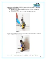
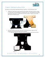
Insert two (2) 4-40 x 3/8” screws in the two holes next to the switch at act as terminal blocks.
When mounting the screws, the eyelets of the switch wires should be captive, as shown in
Figure 5.7.
Figure 5.7
9.
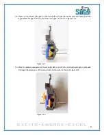
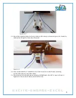
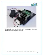
Figure 5.8 depicts the screws pointing up through the top side of your Pi-Bot’s body. This will
later be used to power the gearbox during testing.
Figure 5.8
Содержание Pi-Bot v2.00
Страница 67: ...67 Figure 6 15 ...
Страница 78: ...78 UltraSonicSensorTestwithLED Program ...
Страница 80: ...80 ObstacleAvoidance Program ...
Страница 82: ...82 ObstacleAvoidancewithLED Program ...
Страница 83: ...83 ObstacleAvoidancewithLED Program CONTINUED ...
Страница 90: ...90 Download and run the following program LineFollowing Program ...
Страница 91: ...91 LineFollowing Program CONTINUED ...
Страница 94: ...94 AdvancedLineFollowing Program CONTINUED ...
Страница 95: ...95 AdvancedLineFollowing Program CONTINUED ...
Страница 96: ...96 AdvancedLineFollowing Program CONTINUED ...
Страница 110: ...Appendix B Complete Pi Bot Wiring Schematic ...


